Karios OS and Bootstrap Installation Guide
Note
This guide covers first-time installation of the initial Bootstrap / management node.
Overview
The installation is performed in two parts:
Phase 1 - Karios OS Installation(Steps 1-8): installs Karios OS on the selected target disk or disk set.Phase 2 - Karios Bootstrap Wizard(Steps 1-11): configures the initial site, networking, hardware validation, and platform services.
Allow approximately 20-40 minutes for the full workflow. The OS
installation portion finishes first. The Bootstrap Wizard provisioning stage
normally requires 15-30 minutes, depending on hardware, disk performance,
and network reachability.
How To Use This Guide
Follow the sections in order. Do not skip from Phase 1 to Phase 2 until the OS installation complete screen is shown and the installer media has been removed or detached.
For each screen:
Match the screen title and step number to the screenshot.
Enter only approved site values, not the example values shown in the screenshots.
Use
Continueto move forward andBackto correct earlier values.Stop before clicking
InstallorStart Bootstrapif any disk, network, hostname, DNS, VLAN, or credential value is uncertain.
New-user checkpoints:
Before booting: confirm BIOS, boot media, console access, network design, credentials, and BMC details are ready.
Before
Installin Phase 1: confirm the target disks and management network are correct.Before
Start Bootstrapin Phase 2: confirm every site, administrator, hardware, network, and EVPN-VXLAN value matches the approved deployment design.After completion: record the
Karios UIURL andManagement VIPbefore closing the wizard.
Requirements
Hardware Minimums
Use the same deployment minimums documented in Getting Started.
Component |
Bootstrap / Management Server |
|---|---|
CPU Cores |
16+ cores |
Memory (RAM) |
16 GB minimum |
Disks |
2+ |
BMC (IPMI/iDRAC/iLO) |
Required |
EFI Bootloader |
Required |
KVM Acceleration |
Not required |
Note
Some screenshots show example values or virtual hardware. Use the approved site values for your deployment. This workflow applies to the initial Bootstrap / management node.
BMC capability is required for supported deployments. In
Phase 2 - Step 6 - Hardware: Hardware Detection, entering
BMC / IPMI credentials is required only when out-of-band validation is
being performed during that step.
Network Requirements
Collect all required network values before starting the installer.
Network |
Purpose |
Notes |
|---|---|---|
Management |
Platform services and DNS |
Required |
Storage |
Storage traffic |
Required |
Public |
Public-facing connectivity |
Required |
Guest |
VM tenant traffic |
Required; configure the Guest network in |
OOB |
Out-of-band management |
Required, DHCP disabled |
Validation rules:
All defined VLAN IDs must be unique.
No CIDR overlaps are allowed between Management, Storage, Public, OOB, and any routed Guest networks.
If you use isolated guest networking, the reserved guest VLAN range must not overlap any VLAN already assigned elsewhere in the deployment.
All entered IP values must be within their declared CIDR range.
Management usable IP range must be greater than 20 IPs.
Storage usable IP range must be greater than 20 IPs and greater than or equal to the Management range.
Additional Inputs To Gather
Before you begin, have the following information ready:
Karios ISO provided by Karios Support, which you then write to USB media or mount through BMC virtual media
Local console access or remote console access through BMC/IPMI/iDRAC/iLO
Facility location, organization domain, and physical address
Facility name and environment type
Local OS credentials for
Phase 1 - Step 4: admin username, admin password, and root passwordPlatform administrator details for
Phase 2 - Step 4 - Node Identity: Server Configuration: admin username, admin password, email address, and first and last nameFull network design values for every required network before you begin:
Management: installer interface, plus either DHCP availability or the approved static IP, CIDR prefix, gateway, and DNS values forPhase 1 - Step 3; and the approved ManagementVLAN IDand finalCIDRforPhase 2 - Step 7 - Network & NIC: Network & NIC ConfigurationStorage: VLAN ID, CIDR, and gatewayPublic: VLAN ID, CIDR, and gatewayGuest: at least one guest model, eitherRoutedguest VLAN ID and CIDR, orIsolatedguest VLAN rangeOOB: VLAN ID, CIDR, and gateway, with DHCP disabled
NTP server values
Rack and physical placement information
BMC credentials if validation of out-of-band reachability during hardware detection is required
EVPN-VXLAN design details, if the deployment uses EVPN-VXLAN
Before You Boot The Installer
Warning
The installer erases all data on the selected install target disks. Confirm that no required data remains on those disks before proceeding.
Pre-flight actions:
Disable
Secure Bootin BIOS/UEFI.Enable CPU virtualization:
Intel:
VT-xorIntel Virtualization TechnologyAMD:
SVMorAMD-V
Confirm EFI boot is enabled.
Write the Karios ISO to a bootable USB drive, or prepare BMC virtual media.
Insert the USB drive into the target server, or mount the ISO through BMC virtual media.
Open the server boot menu or BIOS boot selector.
Select the UEFI entry for the Karios installer USB device or virtual CD/DVD media as the boot source.
Boot the server from that installer media.
Creating Bootable Media
Obtain the Karios ISO from Karios Support before creating installation media.
Clients who need the current Karios OS image should contact
support@karios.com.
Use one of the following methods:
Etcheron Windows, macOS, or LinuxRufuson Windowsddon Linux or macOSBMC virtual media for remote installation
Minimum USB Flash Drive Requirements
Use a USB flash drive that meets at least the following baseline:
Requirement |
Minimum Baseline |
|---|---|
Capacity |
At least |
Interface |
|
Read speed |
At least |
Write speed |
At least |
Boot support |
Must support creation of standard bootable USB media |
File system compatibility |
Must support formatting as |
Recommended USB Performance
For better flashing speed and more reliable install media creation, prefer:
USB 3.0orUSB 3.1Read speed of roughly
80-150 MB/sWrite speed of roughly
20-50 MB/s
Important Notes
Avoid very old or low-quality COB-based USB drives.
Slow or poor-quality media can fail during ISO flashing.
Unreliable media can also cause boot failures or unstable installer startup.
Tip
For remote deployments, BMC virtual media is the recommended method because it preserves direct console access through both the OS installation and the Bootstrap Wizard.
Rufus (Windows)
Open
Rufus.Select the target USB drive.
Click
SELECTand choose the Karios ISO.Keep the recommended partition settings for your platform.
Click
STARTand confirm the data-erasure prompt.
Etcher (Windows, macOS, Linux)
Open
Etcher.Click
Flash from fileand choose the Karios ISO.Select the target USB drive.
Click
Flashand wait for completion.
dd (Linux or macOS)
sudo dd if=/path/to/karios.iso of=/dev/<usb-device> bs=4m status=progress
sync
Important dd safety checks:
Replace
/dev/<usb-device>with the whole USB device, not a mounted partition such as/dev/sdb1.On Linux, use commands such as
lsblkbefore and after inserting the USB drive to identify the correct device path.On macOS, use
diskutil listbefore and after inserting the USB drive to identify the correct disk.Confirm the target device path before running
dd. Writing to the wrong disk will erase that disk.Unmount the USB device first if your operating system mounted it automatically.
Phase 1 - Karios OS Installation
Start The Graphical Installer
To start the installer on a physical server:
Create the bootable Karios USB media using Rufus, Etcher, or
dd.Insert that USB drive into the target server.
Power on or restart the server.
Open the server boot menu.
Select the UEFI USB installer device as the temporary boot source.
Click or confirm
Bootto start from that device.
If you are using remote management instead of a physical USB drive, use this BMC virtual-media sequence:
Sign in to the server BMC web UI.
Launch the remote console or KVM session.
Mount the Karios ISO as virtual CD/DVD or virtual media.
Open the one-time boot menu or set the next boot to the virtual media device.
Reboot the server while keeping the remote console open.
Select the UEFI virtual CD/DVD entry if the boot menu prompts you to choose a device.
Confirm the Karios installer loads in the remote console.
Wait until the full installer UI appears. The left sidebar displays Step 1 of
8 under OS Installation.
How to read the installer UI:
The left sidebar shows the current step and the remaining OS install steps.
OS Installationcovers Steps 1-8.The center pane shows the fields for the current step.
BackandContinuemove through the workflow.Shellopens a console for troubleshooting only. It is not required for standard installations.The cards at the upper right are informational only. They are not input fields and do not need to be edited.
Step 1 - License
Review the End-User License Agreement, select the acceptance checkbox, and
continue.
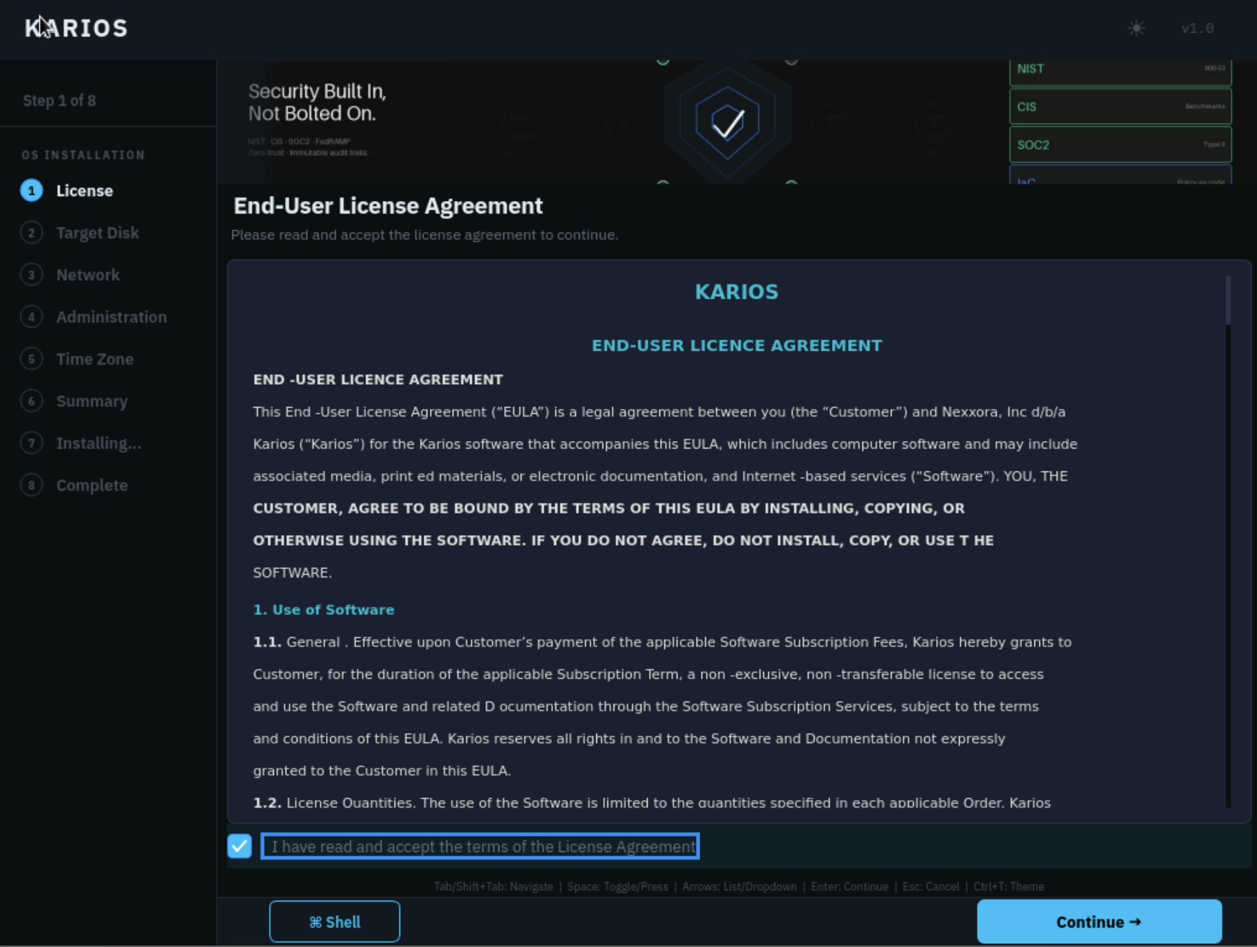
Step 1 of 8: review and accept the license.
What to do:
Read the
End-User License Agreement.Select
I have read and accept the terms of the License Agreement.Click
Continue.
For standard installations, this step requires only the acceptance checkbox.
Karios includes a free trial entitlement for up to 2 Sockets. If the
deployment requires more than 2 Sockets, the customer must request and
purchase a paid license, then upload the license file after installation. See
the License section for the trial-to-paid license
flow and license upload steps.
Basic troubleshooting:
If
Continueremains unavailable, confirm that the acceptance checkbox is selected.If the checkbox cannot be selected or the screen does not render correctly, wait for the installer UI to finish loading or restart the installer session before proceeding.
If the license screen still does not respond, see
Installer does not startin the Troubleshooting section before repeating the installation workflow.
Step 2 - Target Disk
Select the disk or disks that will hold the Karios OS installation and choose
the ZFS Pool Topology for the install target.
Warning
Selecting an install target on this screen erases all data on the selected disk or disks when the installation begins. Select only the disks intended for the Karios OS.
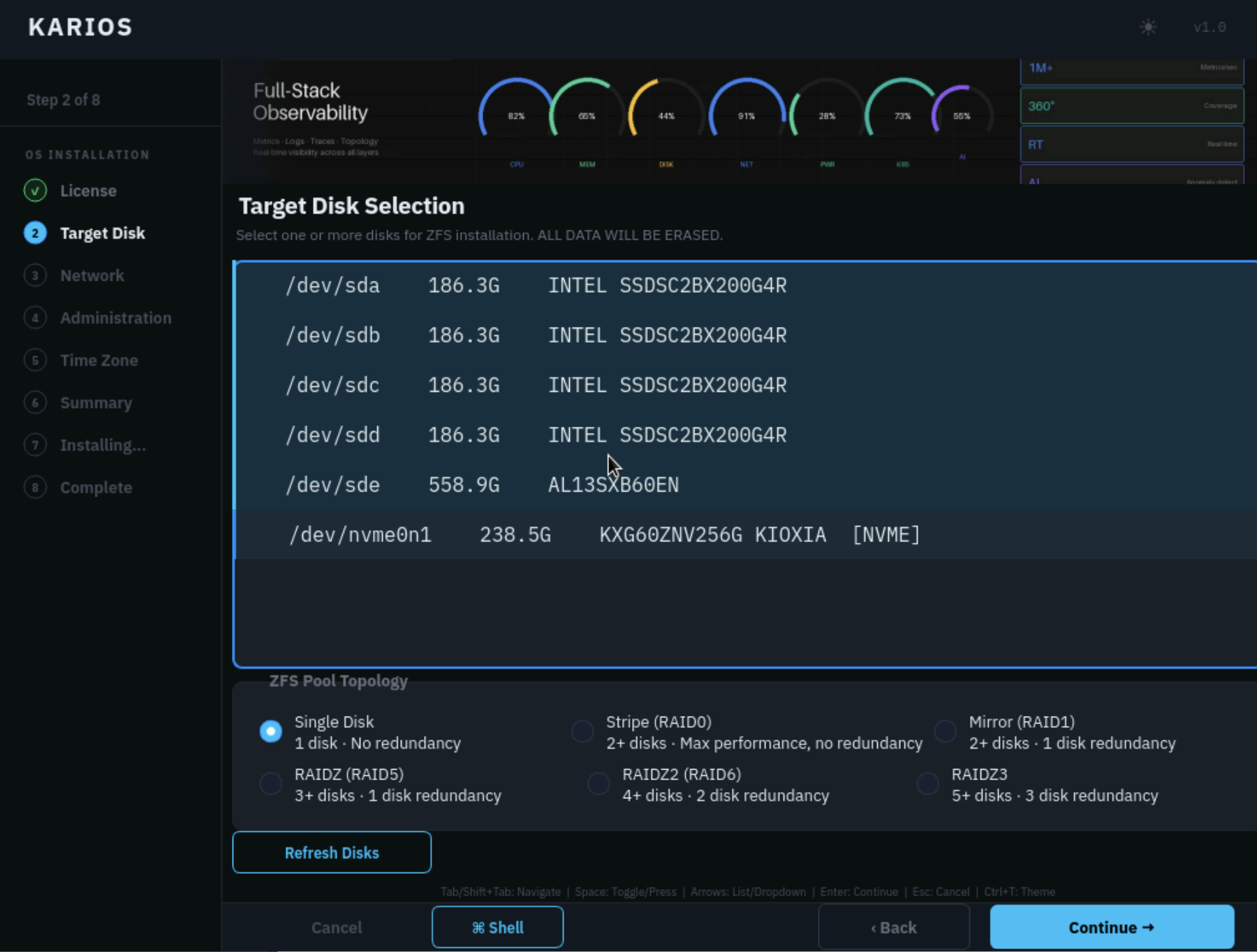
Step 2 of 8: target disk selection and ZFS pool topology.
What to do:
Select the intended OS install disk or mirrored install set.
For initial Bootstrap node deployments, choose
Mirror (RAID1)if two dedicated OS disks are available.Choose a different topology only if your deployment policy explicitly calls for it.
Click
Continue.
Screen options:
UI element |
How to use it |
|---|---|
Disk list |
Select only the disk or disks intended for the operating system. Do not choose disks reserved for data, DFS, or VM storage unless they are explicitly meant to host the OS. |
|
Uses one disk only. No redundancy. Suitable only for lab or evaluation installs. |
|
Combines multiple disks for capacity and speed but provides no redundancy. Avoid for platform nodes. |
|
Writes identical copies across two disks. This is the recommended OS layout when two install disks are available. |
|
Uses parity across three or more disks. Can survive one disk failure. |
|
Uses double parity across four or more disks. Can survive two disk failures. |
|
Uses triple parity across five or more disks. Highest redundancy, lower usable capacity. |
|
Re-scan storage if the expected install disk is missing. |
Quick choice guide:
1 disk: use
Single Diskonly for labs or evaluation.2 disks: use
Mirror. This is the recommended layout for the initial Bootstrap / management node.3 disks dedicated to OS: use
RAIDZonly if your operational standard allows it.4 or more disks dedicated to OS: use
RAIDZ2only if your operational standard explicitly requires an OS layout larger than a mirrored pair.
Basic troubleshooting:
If the expected install disk does not appear, click
Refresh Disksand wait for the storage list to update.If the disk is still missing, verify drive presentation, controller mode, BIOS visibility, and physical cabling before continuing.
If disk identity is uncertain, stop and confirm the correct OS target before selecting any disk or disks.
Step 3 - Network
Configure the installer-side management network. Because the Bootstrap Wizard later continues with the same node, use the final intended management connectivity for this server.
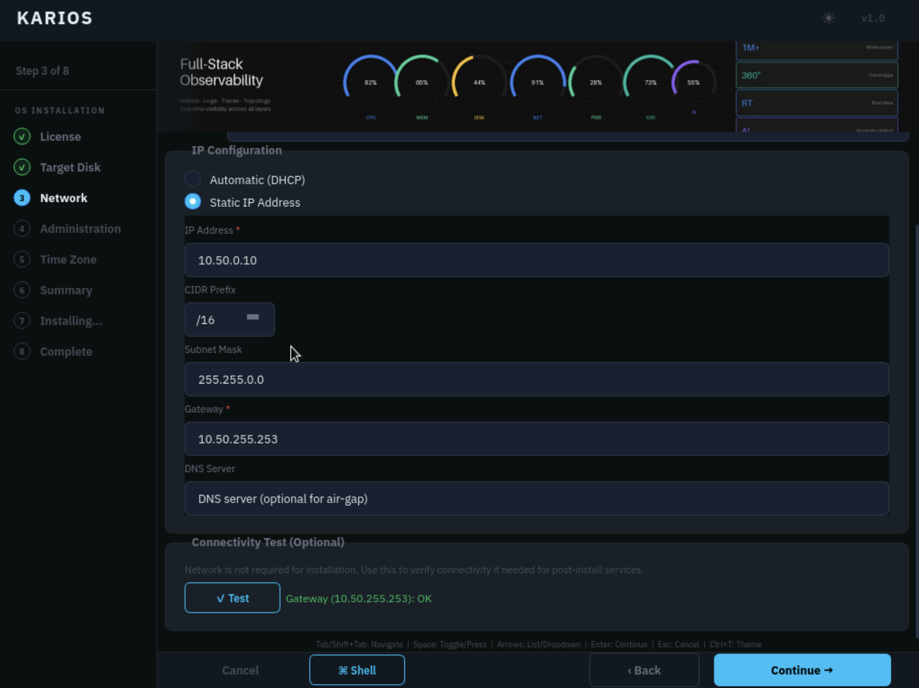
Step 3 of 8: installer network configuration.
Important relationship to Phase 2 - Step 7 - Network & NIC: Network & NIC Configuration:
Phase 1 - Step 3is not a temporary installer-only network.The interface, IP, gateway, and DNS reachability you use here must place the node on the same final Management network that you define later in
Phase 2 - Step 7 - Network & NIC: Network & NIC Configuration.The node IP entered here must be within the Management CIDR defined later in
Phase 2 - Step 7 - Network & NIC: Network & NIC Configuration.The interface you choose here should keep the
Managementrole later inPhase 2 - Step 7 - Network & NIC: Network & NIC Configurationunless you already have an approved cutover plan.
What to do:
Select the correct installer
Interface.Confirm or set the
Hostname.Choose
Automatic (DHCP)if your deployment network provides DHCP for the initial management interface.Choose
Static IP Addressif you were given fixed management values.If using static addressing, enter:
IP AddressCIDR PrefixGatewayDNS Server
Click
Continue.
Before continuing, confirm all of the following on this screen:
The selected
Interfaceis the physical NIC connected to the Management network.The displayed
Hostnameis the node name you intend to keep.If you chose
Automatic (DHCP), the assigned address is on the intended Management network for this node.If you chose
Static IP Address, theIP Address,CIDR Prefix,Gateway, andDNS Servervalues all match the approved network design.If any of those checks fail, correct the values here before you continue.
How to identify the correct interface:
Choose the NIC that is physically connected to the Management network for this node.
Use server port labels, switch-port records, or the BMC console view if your hardware exposes NIC identification there.
If only one interface shows link or is connected to the intended management switch, use that interface.
If the correct interface cannot be confirmed, verify the cabling before continuing.
Management tagging note:
This step does not ask you to mark the Management network as tagged or untagged.
Use the interface and switch port that already provide installer-time access to the Management network.
If your design uses a tagged Management VLAN, the upstream switching path must already be configured to carry that Management VLAN during installation.
Later, in
Phase 2 - Step 7 - Network & NIC: Network & NIC Configuration, set that same Management network toTagged (VLAN)orUntaggedto match the real switch configuration.
Field and option guide:
Field or option |
What it means and what to enter |
|---|---|
|
The NIC used for the initial management connection. Choose the interface connected to the network from which you will later reach Karios. |
|
The local OS hostname for this node. Keep it short, lowercase, and unique on your network, for example |
|
Use this only when the management network provides DHCP and the assigned address is acceptable for continuing installation and later access. |
|
Use this when your network team gave you a fixed address or when the management network does not provide DHCP. |
|
The fixed address for this node on the management network. |
|
The network size, for example |
|
The mask that corresponds to the CIDR prefix. On this screen, it is populated automatically when the prefix is selected. |
|
The router address for the management network. |
|
A reachable resolver the node can use during installation. The field is shown as optional for air-gapped environments. |
Choose between DHCP and static IP like this:
Use
DHCPonly when your final management network is already configured to hand out the correct address automatically.Use
Static IPfor production installs when the management IP is pre-assigned and must remain stable.
If operators will access Karios by DNS name after installation, the DNS server entered here must be reachable from the management network. If DNS is not ready yet, use the management IP for initial access.
Basic troubleshooting:
If no suitable interface appears, verify cabling and confirm that the intended Management path has active link.
If DHCP does not assign a usable address, or static values do not provide connectivity, recheck the selected interface, VLAN access, IP, gateway, and DNS values before continuing.
If Management connectivity still cannot be confirmed, see
Phase 1 Step 3 Network Validation Issuesin the Troubleshooting section for network validation commands and expected results.
Step 4 - Administration
Set the local OS administrator account and the root password used by the installed node.
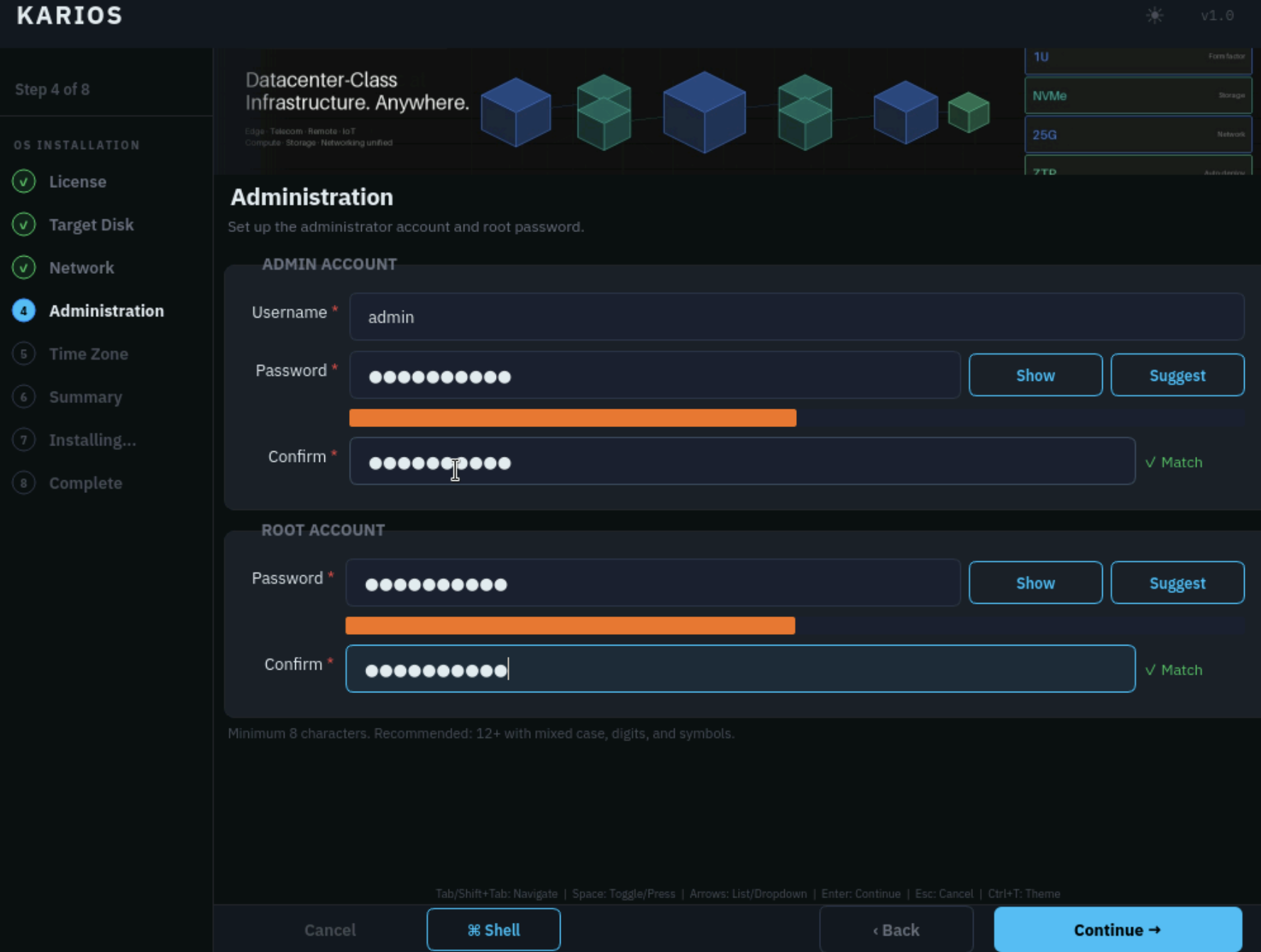
Step 4 of 8: local administration credentials.
What to do:
Confirm or set the
ADMIN ACCOUNTUsername.Enter and confirm the
ADMIN ACCOUNTpassword.Enter and confirm the
ROOT ACCOUNTpassword.Use strong passwords. The screen shows a minimum of
8characters. For a production install, prefer12or more with mixed case, digits, and symbols.Store both credentials securely.
Field guide:
Field |
What to enter |
|---|---|
|
The local OS login for initial console access. Use lowercase letters, numbers, and hyphens only. |
|
The password for the local OS admin user. Enter the same value in both boxes. |
|
The password for the Karios |
|
Temporarily reveals the current password entry to confirm that it was entered correctly. |
|
Generates a strong password automatically when a manually defined password is not required. |
Recommended naming conventions:
Use a simple OS username such as
adminoropsadmin.Avoid personal names for shared operational systems.
Basic troubleshooting:
If a username is rejected, use lowercase letters, numbers, and hyphens only.
If a password is rejected, confirm that it meets the minimum length and that the
PasswordandConfirmvalues match exactly.If credentials are changed during this step, update your secure records before continuing.
Step 5 - Time Zone
Select the system time zone for the node.
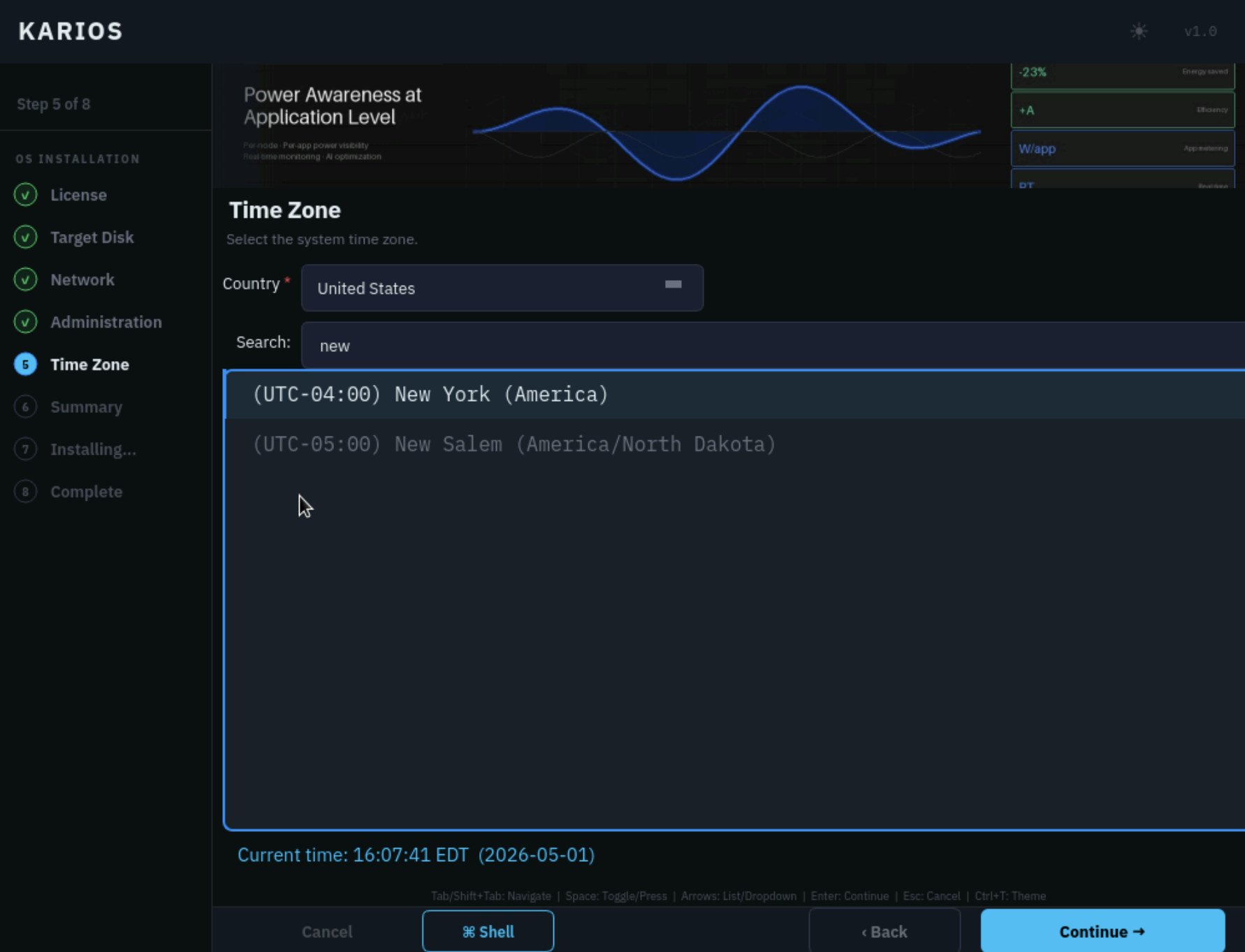
Step 5 of 8: time zone selection.
What to do:
Select the
Countryfield if the list must be narrowed.Use
Searchto find the correct time zone.Confirm the displayed time zone and current time.
Click
Continue.
What the UI means:
Countrynarrows the time-zone list.Searchhelps you find the correct city quickly.The selected time zone determines the node’s local time, logs, and scheduled job behavior.
Choose the time zone where the server physically operates, not the time zone of the person performing the install remotely.
Basic troubleshooting:
If the correct time zone is not immediately visible, narrow the list with
Countryor useSearch.If the operator is remote, confirm that the selected time zone reflects the server location rather than the operator location.
If the displayed local time appears incorrect after selection, recheck the chosen time zone before continuing.
Step 6 - Summary
Review the OS installation choices before writing them to disk.
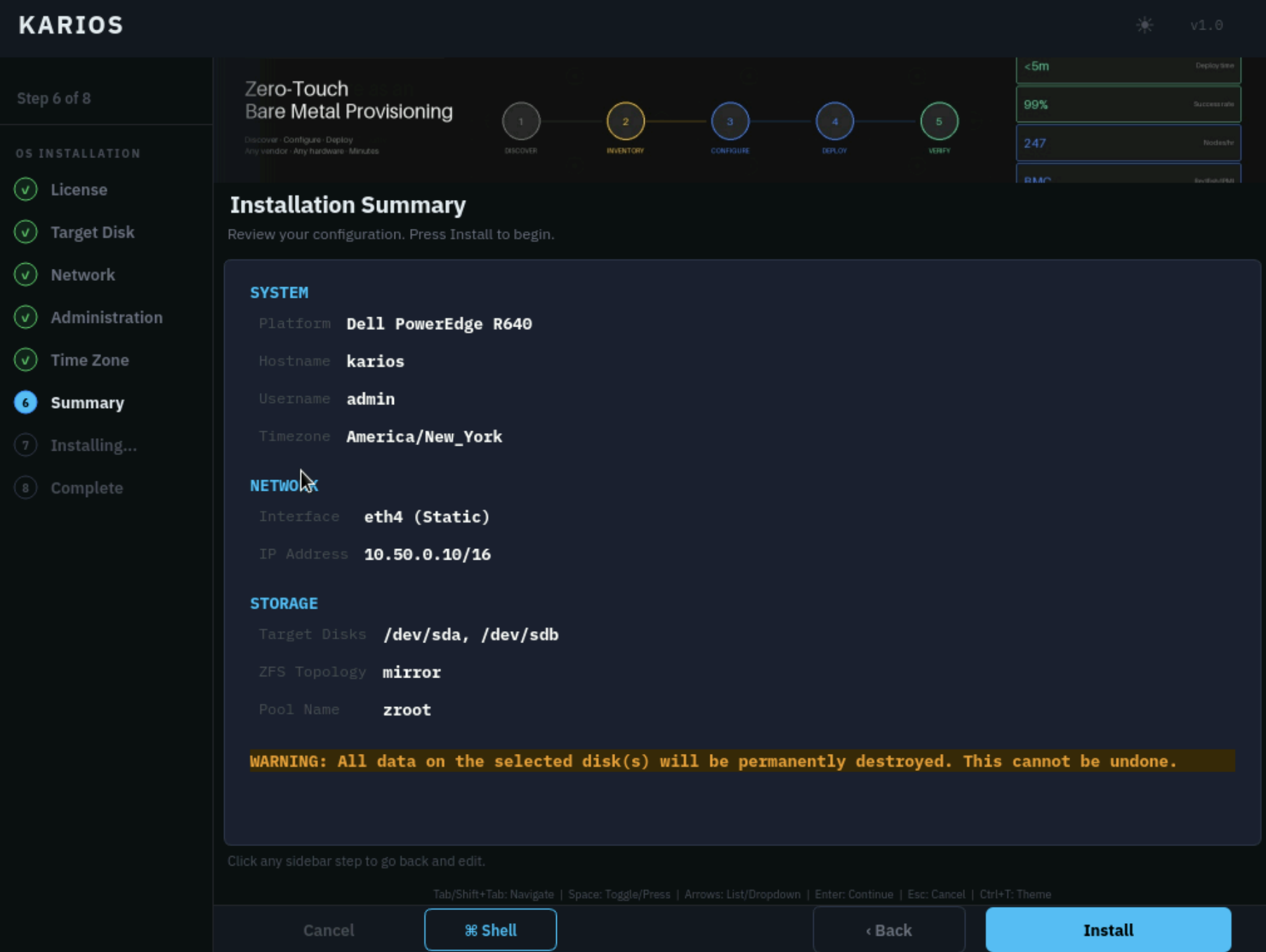
Step 6 of 8: installation summary.
Verify the following before clicking Install:
SYSTEMvalues such as platform, hostname, username, and timezoneNETWORKvalues such as interface and IP addressSTORAGEvalues such as target disks, ZFS topology, and pool name
For a first-time install, pay extra attention to these checks:
Confirm the same management
Interfaceyou selected inStep 3is still shown in the summary.Confirm the management IP shown in the summary is the exact address you intended to use for this node.
Confirm the selected target disk or disks are the ones you are prepared to erase.
What this screen is for:
It is your last safe checkpoint before disk writes begin.
You can click any earlier sidebar step to correct a mistake.
Scroll through the full summary instead of validating only the top section.
Basic troubleshooting:
If any value is incorrect, return to the corresponding earlier step by using the sidebar or
Back.If disk, network, or hostname values differ from the approved deployment inputs, correct them before clicking
Install.Do not begin installation until the summary matches the intended deployment state.
Step 7 - Installing…
The installer writes the OS to disk, configures the system, installs the bootloader, and finalizes the local OS.
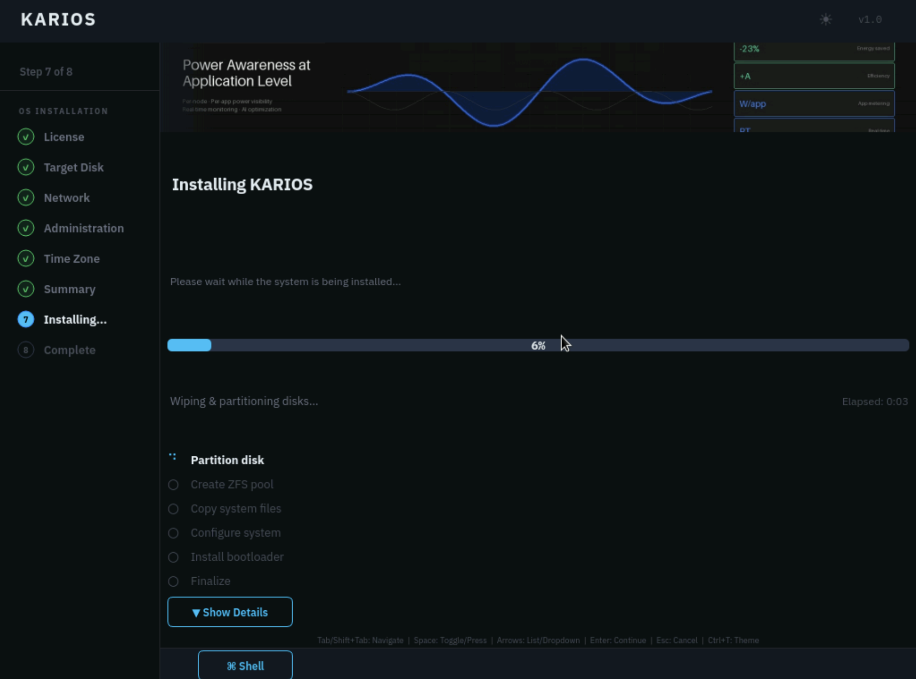
Step 7 of 8: OS installation in progress.
Operator guidance:
Keep the console session open.
Do not power off the node.
Do not remove installation media during this phase.
Use
Show Detailsonly when you need to inspect progress or troubleshoot.
What the install stages mean:
Partition disk: prepares the selected install target.Create ZFS pool: builds the chosen single, mirror, or RAID layout.Copy system files: writes the base OS to disk.Configure system: applies hostname, accounts, networking, and core configuration.Install bootloader: makes the node bootable from the installed disk set.Finalize: completes post-install tasks for the local OS.
Basic troubleshooting:
If progress appears stalled, open
Show Detailsand note the current stage before taking further action.Do not reboot the node or remove installation media while this step is still running.
If an error is shown or the installer does not advance after an extended period, see the
Safe Console Checkssection in Troubleshooting to collect logs (use theShellbutton from the installer and runinstaller-log) before retrying the installation.
Step 8 - Complete and Restart
When the OS installation finishes, the sidebar advances to Complete and the
screen confirms that Phase 1 is done.
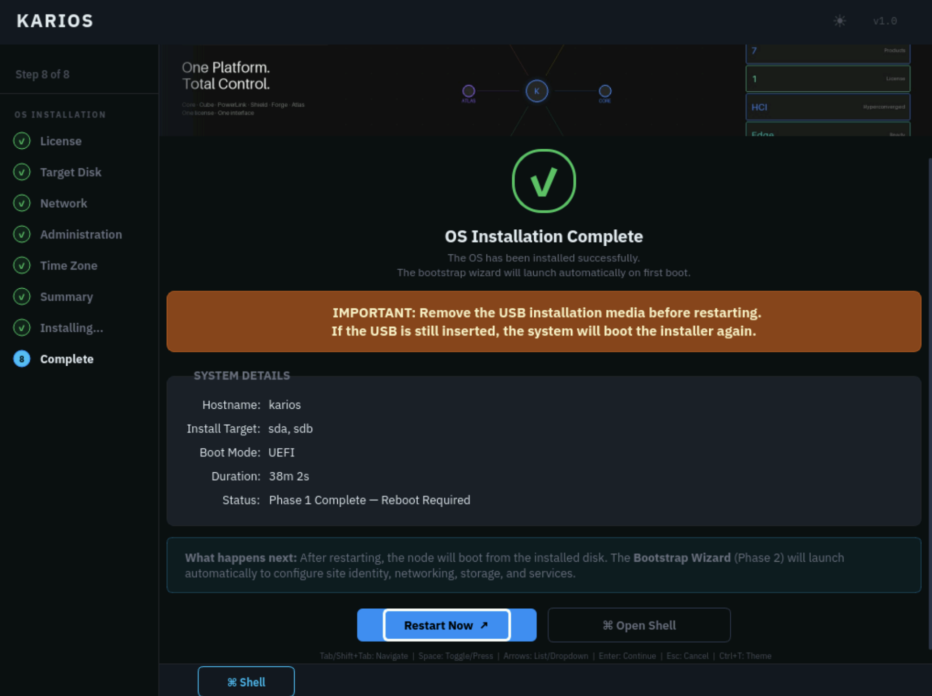
Step 8 of 8: Phase 1 complete and ready to restart.
What to do:
Confirm the screen says
OS Installation Complete.Remove or eject the USB installation media before restarting. If the USB is still inserted, the system will boot the installer again.
If you used BMC virtual media, detach or unmount the ISO before rebooting.
Click
Restart Now.
Important handoff:
After the reboot, the node should boot from the installed disk and start
Phase 2 - Karios Bootstrap Wizard.If the wizard does not open automatically, follow the Phase 2 startup steps below.
Basic troubleshooting:
If the node starts the installer again after reboot, remove or detach the USB or ISO media and reboot from the installed disk.
If restart does not hand off to bootstrap, use the recovery steps below. If those do not work, see
Bootstrap Wizard does not start after rebootin the Troubleshooting section.
Phase 2 - Karios Bootstrap Wizard
After the Phase 1 restart, the node starts from the installed OS and enters
the Bootstrap phase.
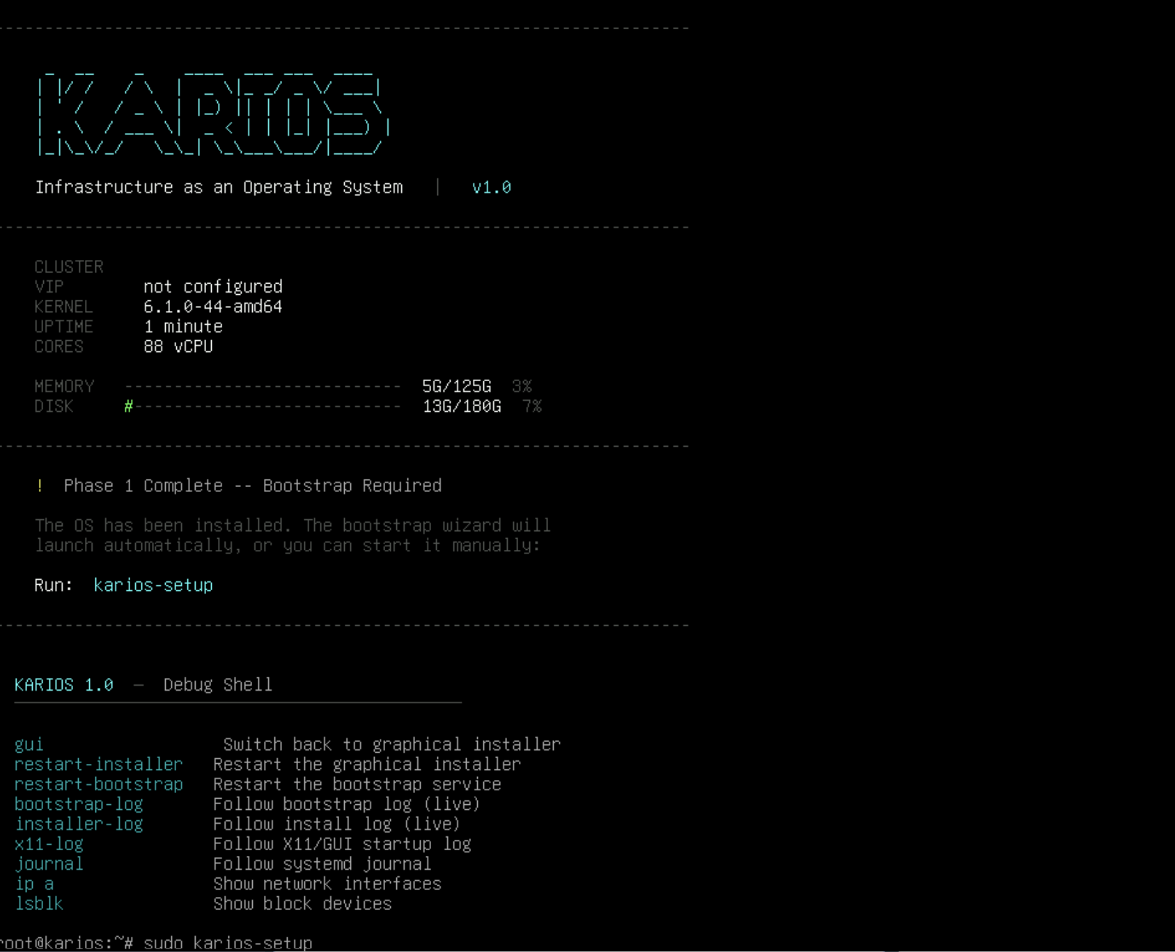
Local console after the OS installation reboot. The screen shows Phase 1 Complete -- Bootstrap Required and the karios-setup command.
The Bootstrap Wizard may launch automatically on first boot.
Bootstrap Wizard loading after the OS installation reboot.
If the wizard does not open automatically:
Sign in as
root.Use the
rootpassword created inPhase 1 - Step 4.Run
karios-setup.Keep the console or remote KVM session open for the rest of the Bootstrap workflow.
The Bootstrap Wizard is an 11-step workflow. Its sidebar groups the steps into
SITE CONFIG, NETWORK & HARDWARE, and EXECUTION.
Use the left sidebar as the progress map. A green check means that step has
been completed. The highlighted number is the screen you are currently editing.
If a value looks wrong, use Back or the sidebar before you continue.
For Phase 2, use the left sidebar label as the step name. Some main panel
titles describe the specific form shown inside that sidebar step. Where the
sidebar label and main panel title differ, this guide shows both as
Step <number> - <sidebar label>: <main panel title>.
Tip
Before you run karios-setup, have the values from the
Additional Inputs To Gather requirements (above) ready — across its steps the wizard
asks for the organization domain, facility name, admin credentials, NTP/DNS servers, rack
placement, and per-network NIC/VLAN/CIDR/IP-range/gateway values. Plan roughly 10-15
minutes to fill the forms, then 15-30 minutes for bootstrapping (Step 10). For
unfamiliar terms (BMC, CIDR, EVPN-VXLAN, LACP, MTU, OOB),
see Glossary.
Step 1 - Location
Provide the deployment location and organization-domain details.
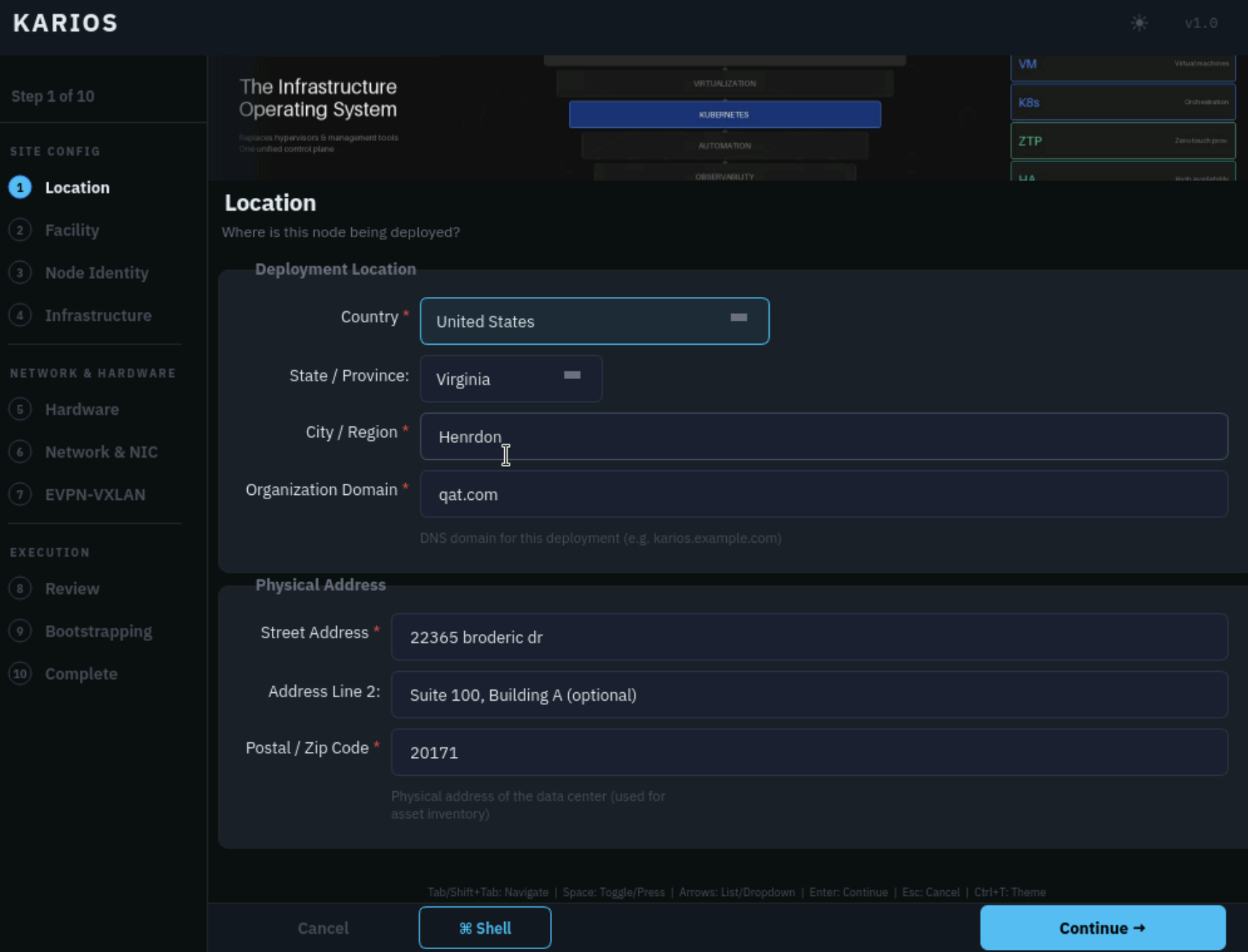
Step 1 of 11: Location.
What to enter:
CountryState / ProvinceCity / RegionOrganization DomainStreet AddressAddress Line 2if neededPostal / Zip Code
Use the actual deployment site address, even when the installer is run from a
remote console. Use an Organization Domain your team can make resolvable in
DNS because later platform naming is derived from it.
Expected outcome: the deployment location and organization domain are recorded and the wizard can generate later site naming from those values.
Step 2 - Providers: Deployment mode
The Providers step selects which provider — Karios or your existing
infrastructure — supplies DNS and DHCP for this deployment.
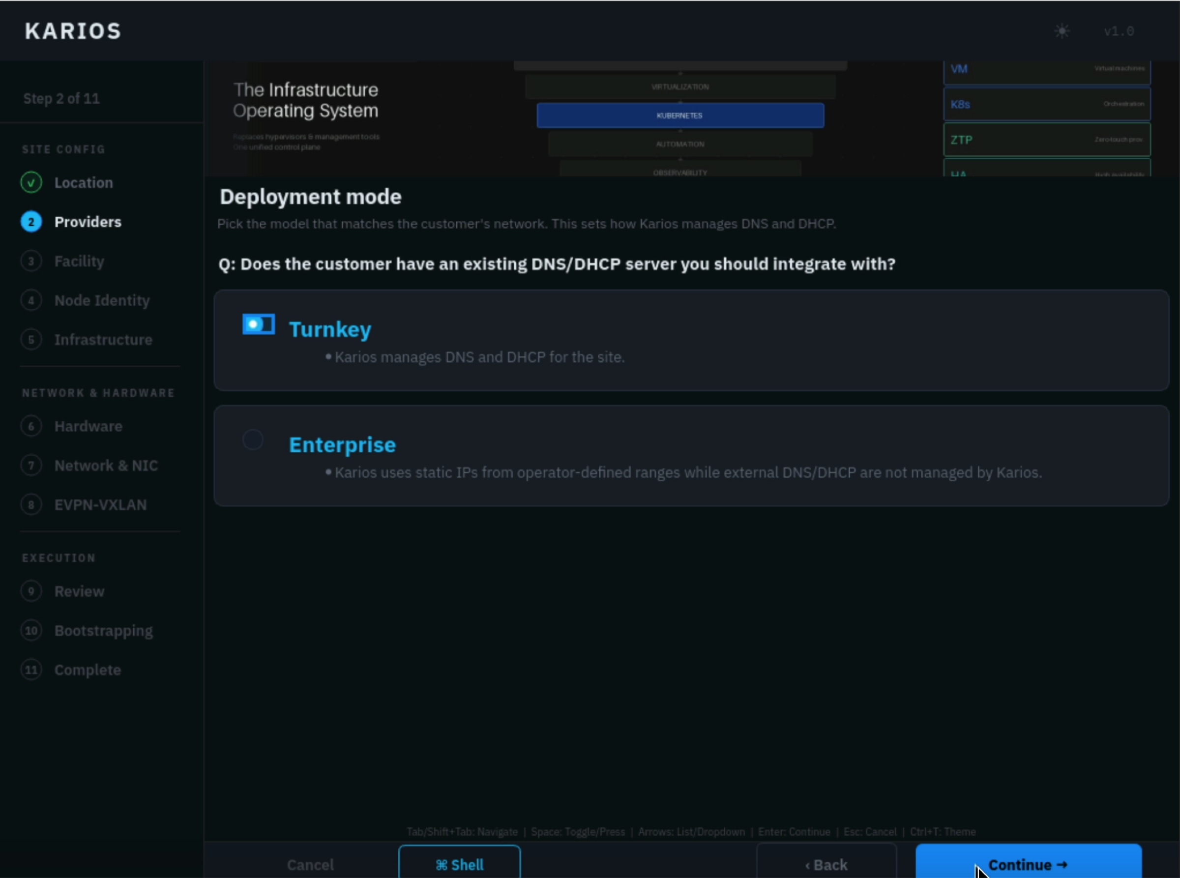
Step 2 of 11: sidebar Providers step showing the Deployment mode form.
What to do:
Answer
Does the customer have an existing DNS/DHCP server you should integrate with?.Select
Turnkeywhen Karios should manage DNS and DHCP for the site.Select
Enterprisewhen Karios should use static IPs from operator-defined ranges and external DNS / DHCP are not managed by Karios.Confirm the selected model matches the customer’s network design before continuing.
Expected outcome: the wizard knows whether Karios will manage DNS and DHCP for the site or integrate with an external enterprise network plan.
Note
This choice drives later networking: with Enterprise you enter the static
VLAN/CIDR/IP-range/gateway values yourself in Step 7 - Network & NIC; with
Turnkey Karios manages DNS and DHCP for those networks.
Step 3 - Facility
Define the facility record and review the generated deployment names.
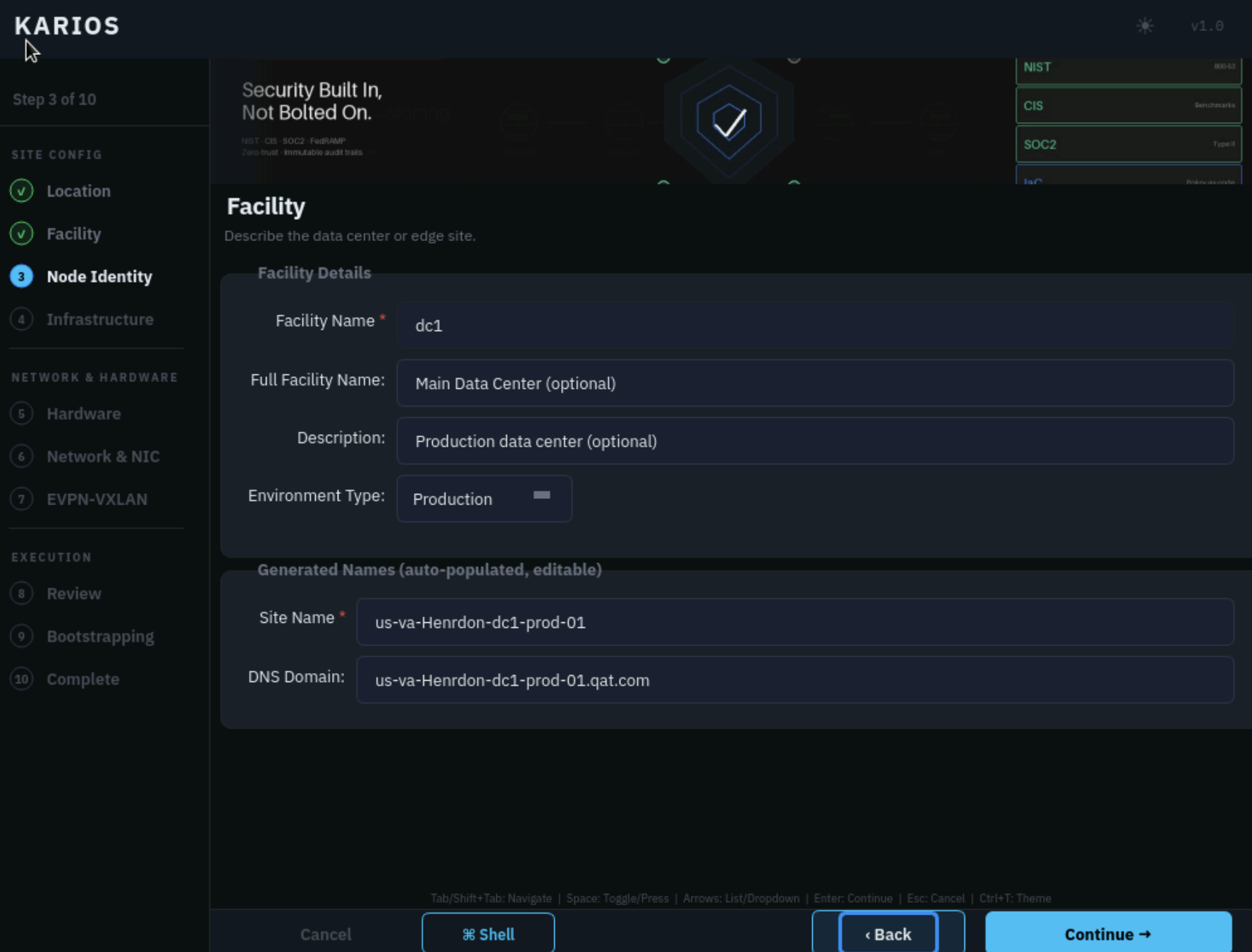
Step 3 of 11: sidebar Facility step showing the Facility form.
What to enter:
Facility NameFull Facility Nameif used by your siteDescriptionif neededEnvironment Type
Review the generated Site Name and DNS Domain before continuing. If the
generated values are wrong, return to Step 1 - Location or correct the
facility fields before moving forward.
Expected outcome: the facility identity, environment type, generated site name, and generated DNS domain match the approved deployment naming.
Step 4 - Node Identity: Server Configuration
Configure the initial platform administrator identity for this deployment.
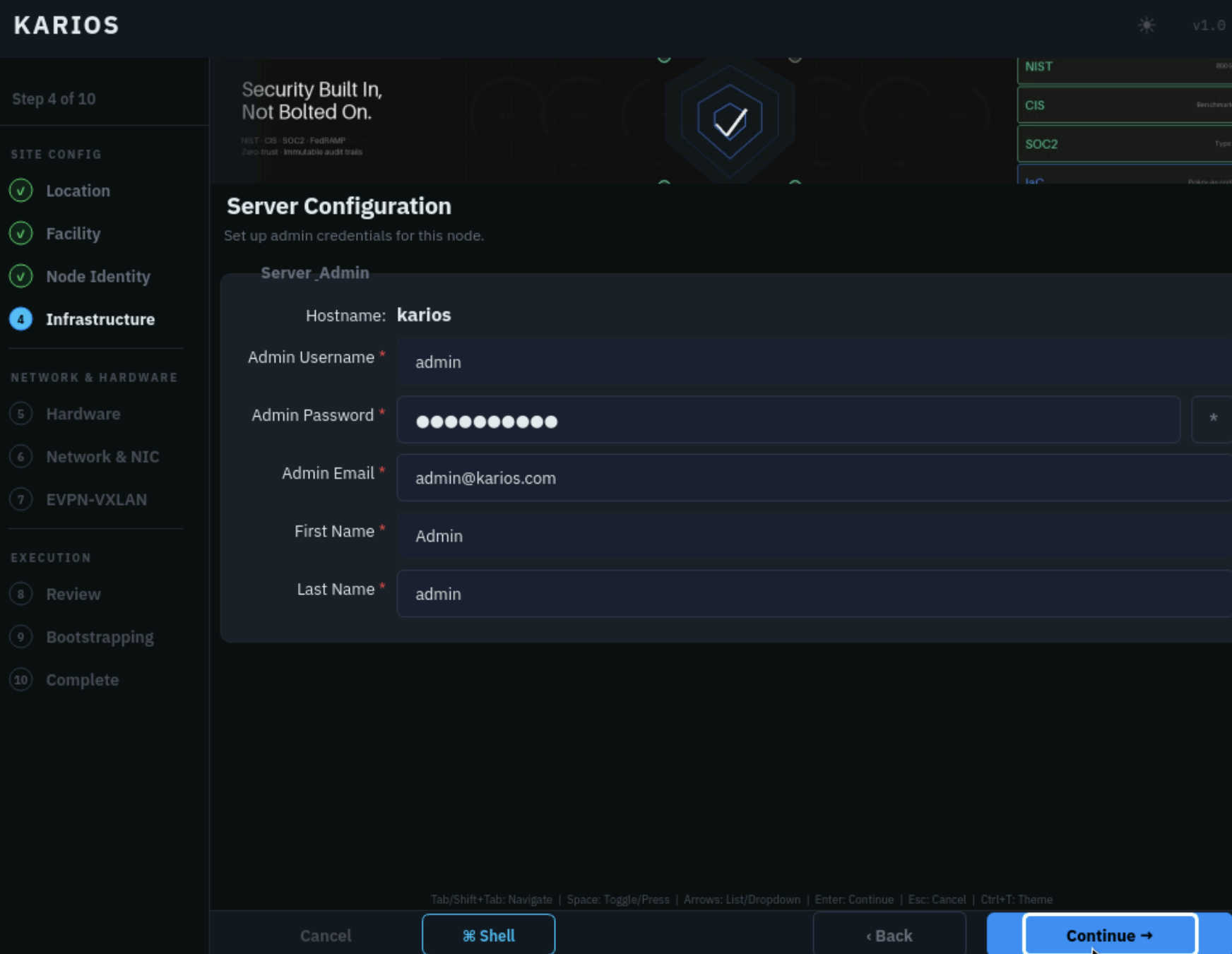
Step 4 of 11: sidebar Node Identity step showing Server Configuration.
What to do:
Verify the
Hostname.Enter the
Admin Username.Enter the
Admin Password.Provide the
Admin Email.Enter the administrator
First NameandLast Name.
Warning
These credentials are used for the initial platform login after bootstrap. Store them securely.
Phase 1 - Step 4 created the local OS accounts for console access. This
step creates the first platform administrator for Karios.
Expected outcome: the first Karios platform administrator account is ready for the initial web UI sign-in after bootstrap completes.
Step 5 - Infrastructure: NTP, DNS & Rack
Provide time, name-resolution, and physical-placement values for the node.
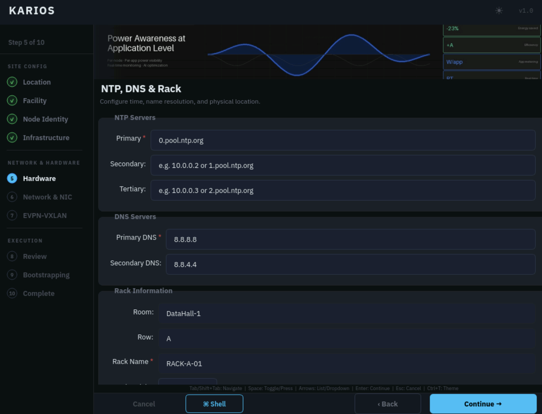
Step 5 of 11: sidebar Infrastructure step showing NTP, DNS & Rack.
What to do:
Enter the primary NTP server.
Add secondary and tertiary NTP servers if available.
Enter the approved
Primary DNSvalue.Enter
Secondary DNSif your deployment uses it.Complete the required rack fields such as
Room,Row,Rack Name,Rack Height, andRack Unit(scroll down for the fields belowRack Name).
Use DNS and NTP values that are reachable from the management network. Complete only the rack and placement fields your site tracks.
Expected outcome: the node has reachable time and name-resolution settings, and the physical rack placement is recorded for inventory.
Step 6 - Hardware: Hardware Detection
Run hardware detection and verify that the wizard sees the expected system resources.
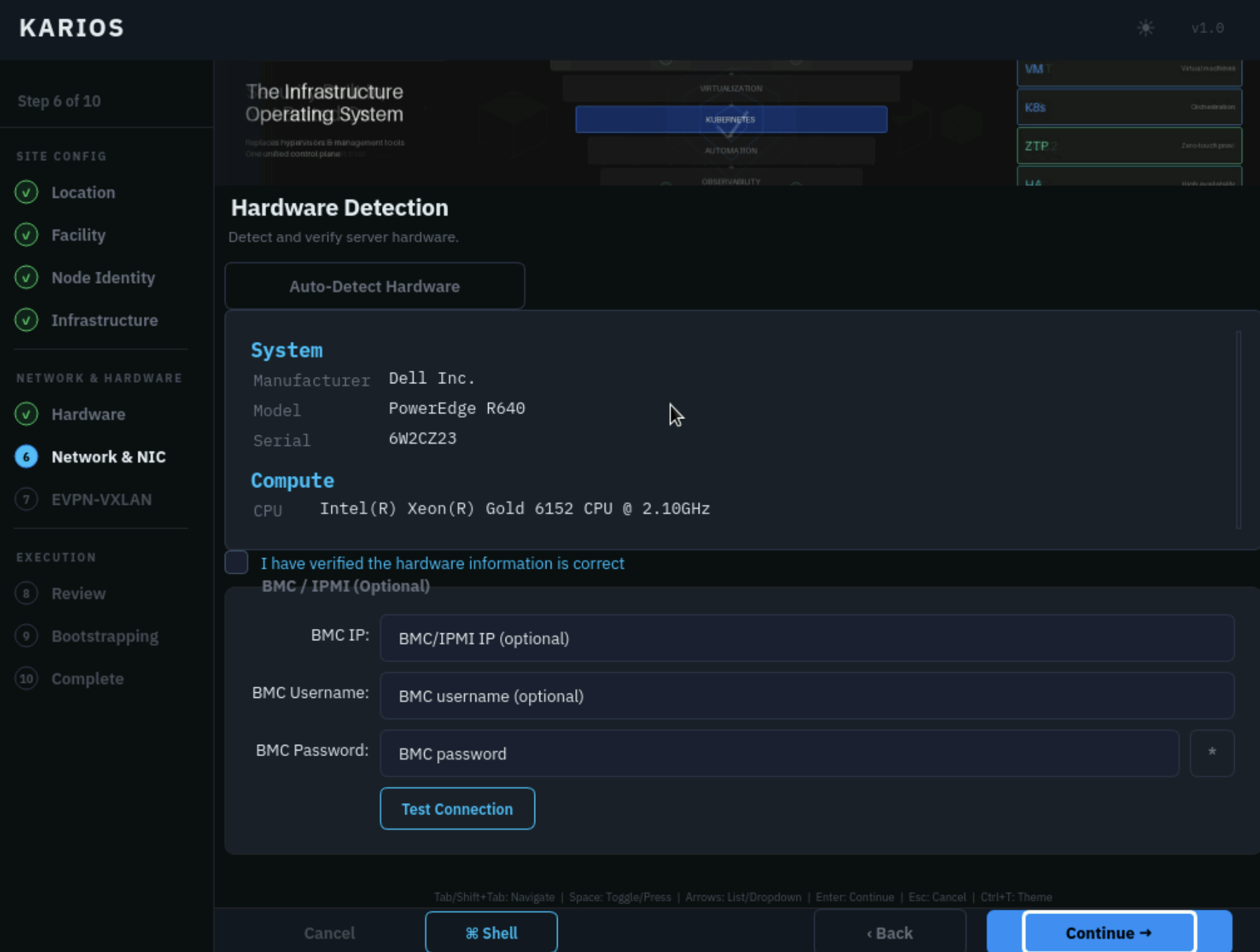
Step 6 of 11: sidebar Hardware step showing Hardware Detection with optional BMC connection details.
What to do:
Click
Auto-Detect Hardware.Review the detected
SystemandComputeinformation.Select
I have verified the hardware information is correctonly after checking the detected values.If BMC (Baseboard Management Controller) validation is required, enter the
BMC IP,BMC Username, andBMC Password.Click
Test Connectionand continue only after the BMC test succeeds when BMC validation is part of your deployment process.
Stop and correct the hardware or BIOS configuration if detected CPU, memory, NIC, storage, or BMC values do not match the deployment requirements.
Expected outcome: the detected hardware matches the server being installed, and BMC validation succeeds when BMC validation is required for the deployment.
Step 7 - Network & NIC: Network & NIC Configuration
Assign the deployment networks directly to physical ports and define VLAN, CIDR, usable IP range, gateway, and advanced interface settings.
Note
This is the most involved step. Have your network plan ready — the NIC-to-role mapping, VLAN IDs, CIDRs, usable IP ranges, and gateways for each network.
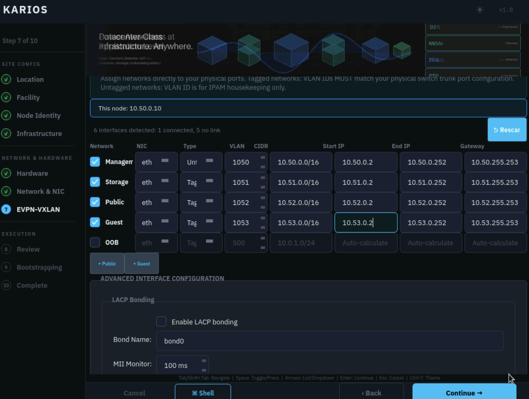
Step 7 of 11: sidebar Network & NIC step showing the Network & NIC Configuration form with This node and LACP bonding options.
The main grid shows the network roles:
ManagementStoragePublicGuestOOB(Out-of-Band management network)
For each enabled role, review the NIC, Type, VLAN, CIDR,
Start IP, End IP, and Gateway values. Tagged networks must use
the VLAN IDs configured on the physical switch trunk. Untagged networks use
the native network path.
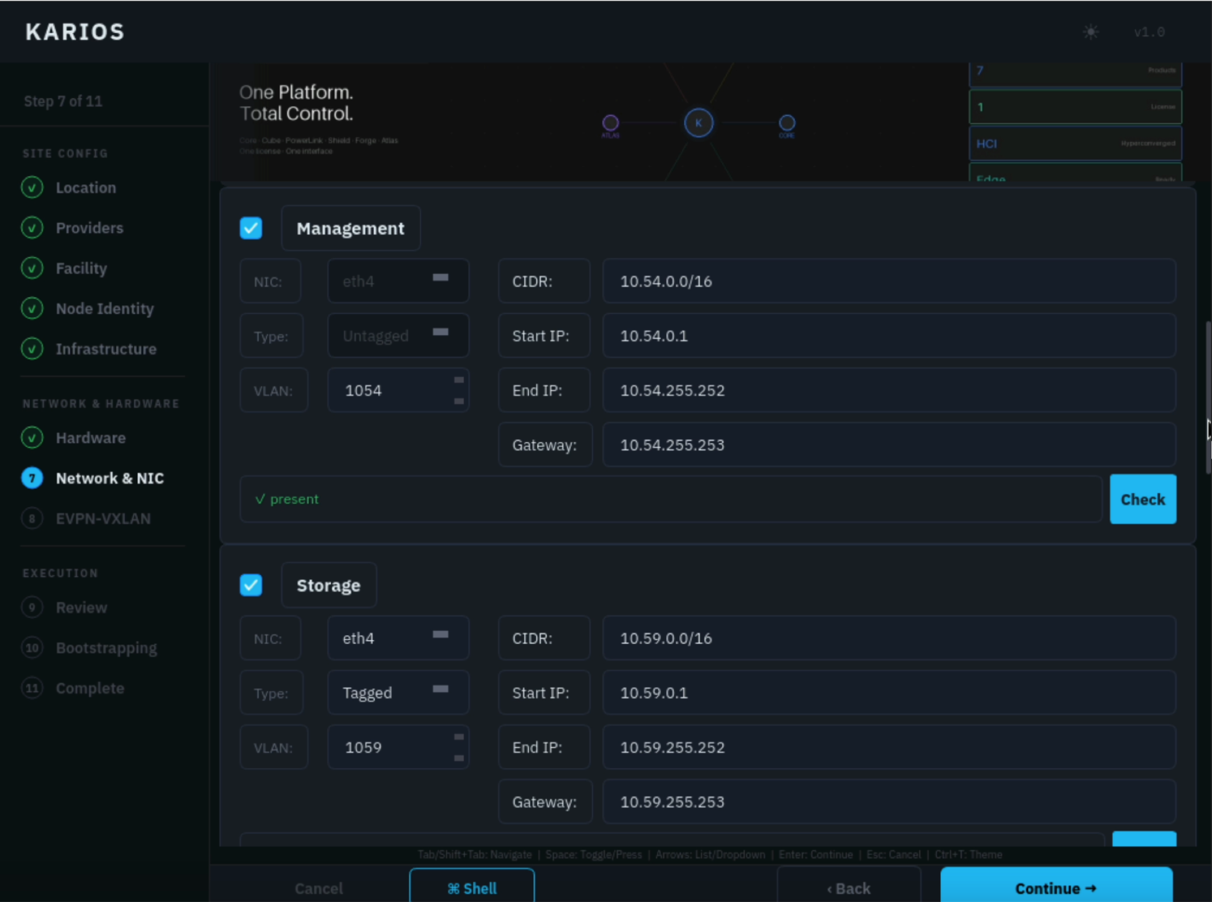
Step 7 of 11: the Management and Storage network role rows.
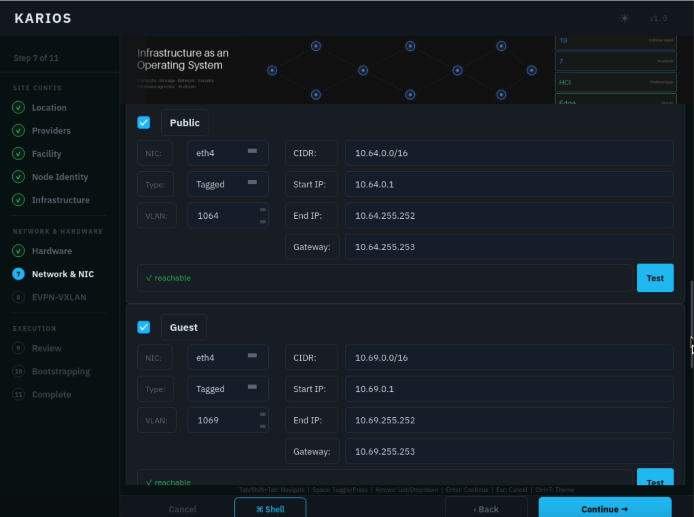
Step 7 of 11: the Public and Guest network role rows.
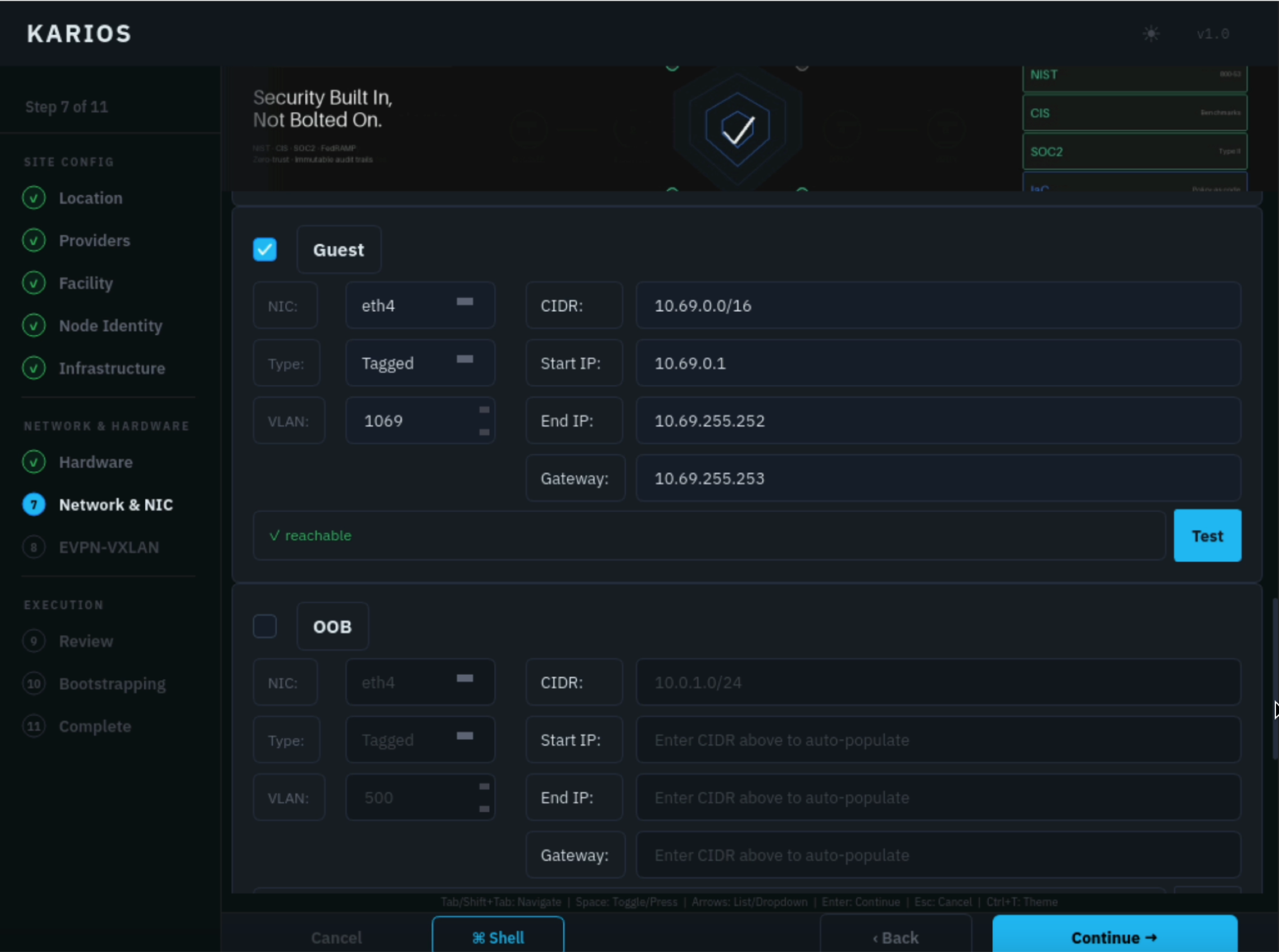
Step 7 of 11: the Guest and OOB network role rows.
What to do:
Confirm
This nodeshows the expected management IP.Enable the required network roles.
Select the correct physical NIC for each role.
Set
TaggedorUntaggedto match the switch-port design.Enter the approved VLAN, CIDR, IP range, and gateway values.
Use
+ Publicor+ Guestonly when your design requires additional networks.Configure LACP (link aggregation), MTU, and offload settings only when those values are part of the approved network design.
Do not continue if required networks are missing, CIDR ranges overlap, VLAN IDs
are wrong, or the Management network no longer matches the interface and IP
path used in Phase 1 - Step 3.
Expected outcome: each required network role is assigned to the correct NIC, tagging mode, VLAN, CIDR, IP range, and gateway before bootstrap begins.
Step 8 - EVPN-VXLAN: EVPN-VXLAN Fabric
Enable the EVPN-VXLAN overlay (overlay networking built on BGP/EVPN) only if the approved deployment design requires it.
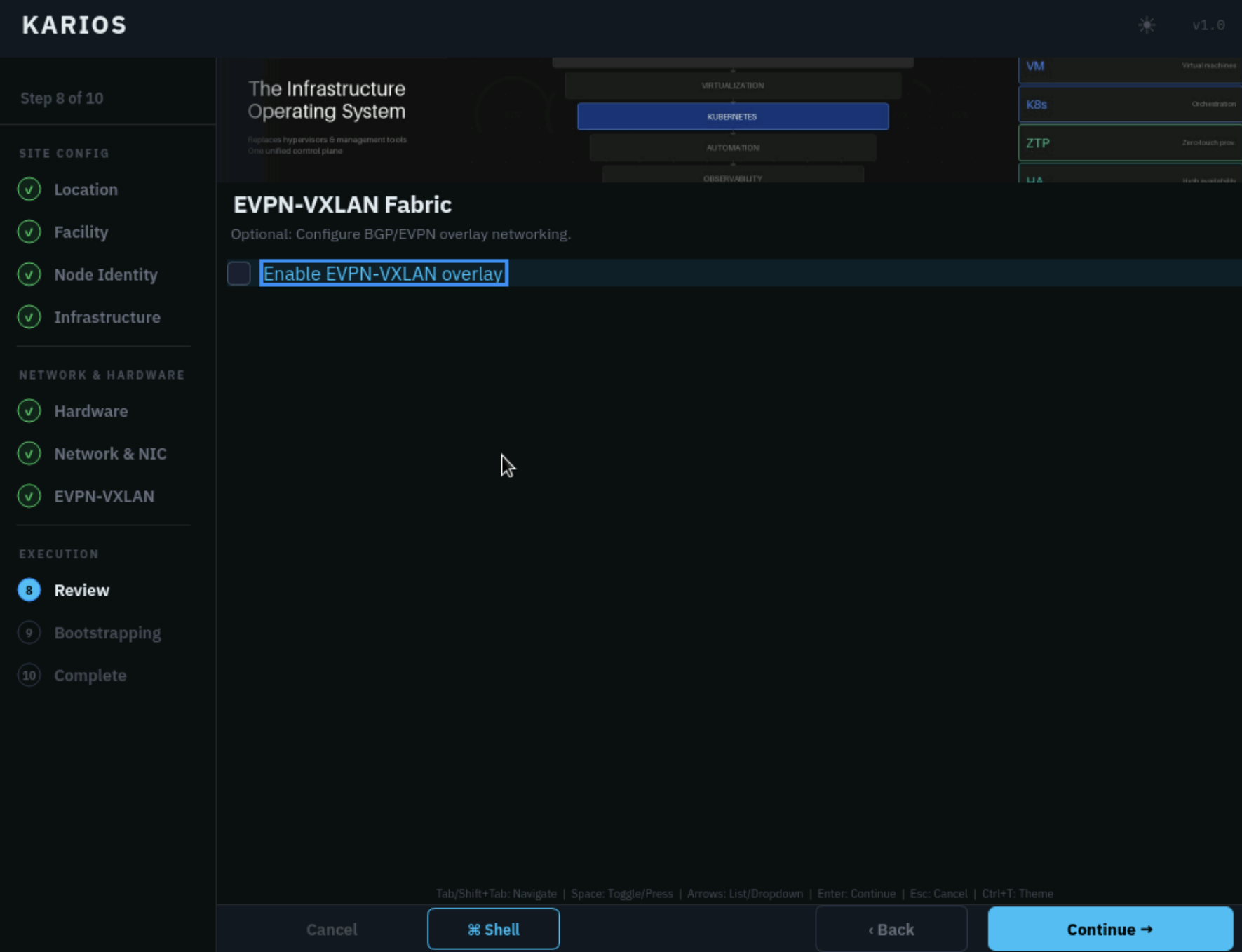
Step 8 of 11: sidebar EVPN-VXLAN step showing EVPN-VXLAN Fabric.
What to do:
Leave
Enable EVPN-VXLAN overlay fabriccleared for a standard install.Enable it only when the deployment has an approved BGP / EVPN overlay design.
Continue only after confirming the underlay and switch configuration match the EVPN-VXLAN design.
Expected outcome: EVPN-VXLAN is enabled only for deployments that are designed to use overlay networking.
Step 9 - Review: Review & Confirm
Validate the full configuration before starting bootstrap.
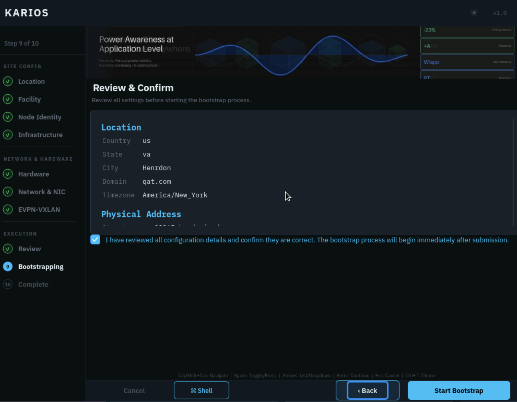
Step 9 of 11: sidebar Review step showing Review & Confirm.
What to do:
Scroll through the review summary.
Confirm location, facility, server, network, hardware, and infrastructure values.
Select the confirmation checkbox.
Click
Start Bootstrap.
Use the sidebar or Back button to correct anything that is wrong before
starting bootstrap.
Expected outcome: the review page is the final checkpoint before Karios starts
provisioning services. Do not click Start Bootstrap until every value is
confirmed.
Step 10 - Bootstrapping: Setting Up Your Infrastructure
Karios provisions the initial infrastructure services automatically.
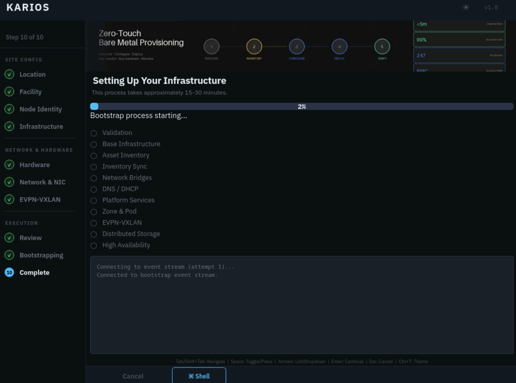
Step 10 of 11: sidebar Bootstrapping step showing Setting Up Your Infrastructure.
Operator guidance:
Keep the console or remote KVM session open.
Do not reboot the node during this phase.
Expect this step to take approximately
15-30 minutes.Monitor the progress list and log panel while the system is being set up.
The process is not finished until the wizard shows KARIOS Bootstrap
Complete.
Expected outcome: the progress list advances through the bootstrap stages and the wizard eventually shows the completion screen.
Step 11 - Complete: Bootstrap Complete
When bootstrap finishes, the completion screen shows the Karios UI URL,
Management VIP (the virtual IP that fronts the management services), install
target, boot mode, version, duration, zone, and Status: Complete.
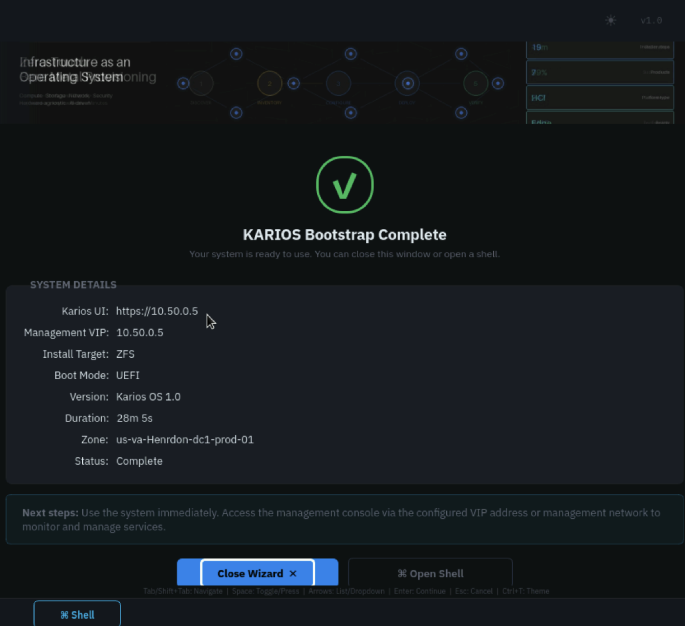
Step 11 of 11: sidebar Complete step showing KARIOS Bootstrap Complete with the Karios UI URL and Management VIP.
What to do:
Confirm that the completion state indicates bootstrap finished successfully.
Record the
Karios UIURL andManagement VIPshown on the screen.From a workstation that can reach the Management network, open the
Karios UIlink shown on the Bootstrap Complete screen.Use the administrator account created in
Phase 2 - Step 4 - Node Identity: Server Configurationfor the first platform sign-in.After sign-in, confirm that the Karios UI loads successfully.
Click
Close Wizardonly after recording the access URL.
If browser access fails, confirm that the workstation can reach the Management network and that you are using the correct DNS name or Management IP.
Warning
Troubleshooting: Ad Blockers & Tracking Protection
If you are experiencing infinite loading screens, missing UI components, or
failing API calls, your ad blocker or browser’s strict tracking protection may
be interfering. Disable extensions such as uBlock Origin, AdBlock Plus,
or Ghostery for the Karios URL before troubleshooting anything else in the
UI.
Troubleshooting
Safe Console Checks
Use the following commands only when an issue occurs and direct confirmation of system state or targeted troubleshooting is required, or when directed by support:
lsblk
ip addr
ip route
ping <gateway-ip>
ping <dns-server-ip>
Use these console helpers only when you are at the installed system console and need to inspect Bootstrap Wizard state or recover the graphical workflow:
karios-setup
gui
restart-installer
bootstrap-log
installer-log
x11-log
journal
Purpose of these commands:
lsblkshows block devices to confirm that the expected install disk is present.ip addrshows network interfaces, link state, and IP addresses.ip routeshows the current routing table and default route.ping <gateway-ip>checks whether the selected network can reach its gateway.ping <dns-server-ip>checks whether the configured DNS server is reachable.karios-setupstarts the Bootstrap Wizard when it does not open automatically after reboot.guiswitches back to the graphical installer.restart-installerrestarts the graphical installer.bootstrap-logfollows the bootstrap log.installer-logfollows the install log.x11-logfollows the X11 or GUI startup log.journalfollows system events from the installed node.
Log File Locations
When an installation or bootstrap issue needs deeper investigation, these log
files record what happened on each node. The installer-log and
bootstrap-log console helpers above follow the first node’s logs live.
Node |
Phase |
Log location |
|---|---|---|
First node |
OS installation |
|
First node |
During bootstrap |
|
Second node |
OS installation (target console) |
|
Second node |
During bootstrap |
|
Installer does not start
Confirm the system booted from the Karios ISO in UEFI mode.
Disable Secure Boot.
Recreate the boot media if the graphical installer never loads.
If using BMC virtual media, verify the remote ISO attachment is still active.
If the expected install disk does not appear after boot, the installer
Shellcan be used to confirm disk visibility withlsblk.
Phase 1 Step 3 Network Validation Issues
When direct network validation is required, open the installer Shell and
run:
ip addr
ip route
ping <gateway-ip>
ping <dns-server-ip>
Expected results:
ip addrshould show the selected installer interface with the IP address you entered or received through DHCP.ip routeshould show a default route through the configured gateway.ping <gateway-ip>should succeed. If it fails, the VLAN, cabling, NIC selection, or gateway value is likely wrong.ping <dns-server-ip>should succeed. If it fails, the DNS server is not reachable from the management network path you configured.
Re-check cabling, switch VLAN access, gateway, and DNS values before continuing.
If the values appear correct and the network issue persists, confirm the Management network design before proceeding further with the installation.
Bootstrap Wizard does not start after reboot
Follow the Phase 2 startup steps in
Phase 2 - Karios Bootstrap Wizard.Make sure the node rebooted from the installed OS disk, not from the USB or mounted ISO again.
If you used BMC virtual media, confirm the ISO was detached after
Phase 1 - Step 8.If the graphical session does not appear after running
karios-setup, useguiorrestart-installerand reviewx11-logfor display startup issues.
Hardware detection is incomplete
Re-seat or re-check the affected hardware.
Confirm BIOS settings still expose virtualization and PCIe devices correctly.
Verify BMC access and cabling if the out-of-band values are missing or wrong.
If direct confirmation is required before returning to the wizard, use
lsblkfor disks andip addrfor NICs.
Bootstrap stalls or fails
Keep the screen open and review the live progress log on
Phase 2 - Step 10 - Bootstrapping: Setting Up Your Infrastructure.Re-check
Phase 2 - Step 7 - Network & NIC: Network & NIC Configurationfor invalid ranges, overlaps, or mismatched interface choices.Use the wizard
Shellonly when you need direct console diagnostics or when directed by support.
Optional Diagnostic Commands:
bootstrap-log
installer-log
journal
ip addr
ip route
ping <gateway-ip>
ping <dns-server-ip>
Interpretation guidance:
bootstrap-loghelps confirm which bootstrap stage is currently active.installer-loghelps confirm whether the wizard reported a specific configuration or service error.journalhelps surface broader node errors during provisioning.ip addrandip routehelp confirm the active interfaces and routing state while bootstrap is running.ping <gateway-ip>andping <dns-server-ip>help confirm that the Management network path is still reachable.
Common stage-to-cause hints:
Stalls at
Validationcommonly indicate missing required values, overlaps, or invalid ranges entered earlier in the workflow.Stalls at
Network Bridgescommonly indicate wrong NIC role mapping, incorrect tagged or untagged settings, or VLAN mismatch.Stalls at
DNS / DHCPcommonly indicate unreachable DNS values, incorrect management-network settings, or aProvidersdeployment mode (Phase 2 - Step 2 - Providers: Deployment mode) that does not match how DNS and DHCP are actually provided —Turnkey(Karios-managed) versusEnterprise(external).Stalls at
Zone & Podcommonly indicate management, public, or infrastructure-network values that do not match the intended design.Stalls at
Distributed Storagecommonly indicate storage-network or storage-range problems.
DNS or DHCP not working as expected
Re-check the
Providersdeployment mode inPhase 2 - Step 2 - Providers: Deployment mode:Turnkeymeans Karios manages DNS and DHCP, whileEnterpriseexpects external DNS / DHCP with operator-defined static IP ranges.In
Enterprisemode, confirm the static VLAN, CIDR, IP-range, and gateway values entered inPhase 2 - Step 7 - Network & NIC: Network & NIC Configurationmatch the external network plan.Confirm the
Primary DNS/Secondary DNSand NTP values fromPhase 2 - Step 5 - Infrastructure: NTP, DNS & Rackare reachable from the management network.
Karios is not reachable after bootstrap
Confirm that the management network, gateway, and DNS values entered during
Phase 1 - Step 3andPhase 2 - Step 7 - Network & NIC: Network & NIC Configurationare reachable from your workstation.Sign in with the administrator account created during
Phase 2 - Step 4 - Node Identity: Server Configuration.
If the node console remains accessible, the following commands can also be used to validate the network path:
ip addr
ip route
ping <gateway-ip>
ping <dns-server-ip>
When To Contact Karios Support
Contact Karios Support at support@karios.com under any of the following
conditions:
The expected install disk or NICs never appear in the installer even after rechecking hardware and BIOS settings.
The Bootstrap Wizard does not start after reboot and
karios-setup,gui, orrestart-installerdo not recover it.Bootstrap remains stuck on the same stage and does not progress after you review the logs and network checks.
The node reaches the end of installation but Karios is still not reachable and the local checks do not show an obvious network or DNS issue.
You are considering rerunning the install or repeating destructive disk actions without understanding the original failure.
When you contact support, include:
The exact phase and step where the problem occurs.
A screenshot of the failing screen if available.
The outputs or observations from
bootstrap-log,installer-log,journal,ip addr,ip route, andlsblkwhen relevant.Whether you installed from USB media or BMC virtual media.
The server model and any unusual hardware findings you noticed during
Phase 2 - Step 6 - Hardware: Hardware Detection.
→ Next: Infrastructure