Karios Forge - User Guide

0. Quick Overview

If you are new, use this section before the detailed goal-by-goal steps.

Karios Forge (BMO) is the management hub for bare-metal server provisioning and lifecycle management.

Canonical references in this guide:

Common workflows in this guide:

  • Add host with valid BMC details

  • Run Hardware Reveal from row Action

  • Confirm node enters Ready

  • Run Provision from row Action

  • Validate management node details first

  • Validate server details from Hardware Inventory

  • Open node Console to monitor jobs

  • Run Unprovision to remove only the OS and return a node to Ready

  • Run Decommission to fully reset a node and return it to Discovered

How to read this guide:

  • Treat 4.4. BMO Stage Flow from Dashboard as the only canonical lifecycle sequence.

  • Sections 5 through 11 are task-based runbooks you use during that lifecycle or for maintenance; they are not extra lifecycle stages.

  • Section 12 is outcome-based troubleshooting.

  • For a first-time node onboarding path, use Access Forge -> Add Host -> Hardware Reveal -> Ready -> Provision -> Configured.

Common access checks

Use these checks when Forge does not open or the dashboard looks incomplete:

  1. Confirm your current role can access Forge and run node lifecycle actions.

  2. Refresh Control Center once and reopen Forge from the left navigation.

  3. If cards or rows are still missing, verify that at least one node has been added and that your scope includes the target facility.

1. Overview

Karios Forge is the bare metal operations area used to onboard and manage physical nodes.

1.1. Core Terms (Read First)

  • BMC (Baseboard Management Controller): out-of-band management interface on the physical server used for remote power, console, and hardware control.

  • BMO (Baseboard Management Organization): management hub for bare-metal server provisioning and lifecycle management in Karios Forge.

  • Discovered: server is onboarded and reachable via BMC, but not yet provisioned.

  • Ready: server has completed hardware reveal and is ready for provision action.

  • Provision: installs the node OS (image).

  • Configure: applies Ceph storage, the SDN network, and the rest of the node configuration; the node then becomes Configured and ready for production use.

For the canonical first-time lifecycle order, use 4.4. BMO Stage Flow from Dashboard.

1.2. What You Can Do from the Forge Dashboard

From the dashboard and node pages, you can:

  • Add/discover nodes

  • Open node details by lifecycle state

  • Run power actions (power on, power off, power cycle, force off)

  • Review management node Hardware Inventory, BIOS Config, and Firmware Updates

  • Run Hardware Reveal and validate server hardware inventory

  • Unprovision nodes to remove the OS and return them to Ready

  • Decommission nodes to fully reset them and return them to Discovered

  • Open node console directly for troubleshooting and boot visibility

1.3. Action Map by Node Stage

Use 4.4. BMO Stage Flow from Dashboard as the single lifecycle reference for stage-to-action mapping.

Note

Hardware Reveal is mandatory before first provisioning. Rerun it after BIOS, firmware, or hardware changes before final inventory validation.

2. Prerequisites

Before using Forge, confirm:

  • You have BMC IP, username, password

  • Target host is powered on and reachable on the BMC/management network before Add Host

Warning

Invalid BMC details can prevent Forge workflows.

2.1. Required Access (RBAC)

Before running Forge workflows, confirm with your administrator that your account can access Forge and run these actions:

  • Add Host

  • Hardware Reveal

  • Provision

  • Configure

  • BIOS Configuration

  • Firmware Updates

  • Console

  • Unprovision

  • Decommission

3. Access Forge

When to Use:

Use this first before any node onboarding or maintenance workflow.

Purpose:

Open the Forge dashboard from the left navigation.

Steps:

  1. Log in to Control Center.

  2. Click the Forge icon in the left navigation.

  3. Open the Forge dashboard.

Control Center left navigation showing Forge entry

Access Forge from the Control Center navigation.

What this screenshot shows:

  • Left sidebar navigation with the Forge entry icon.

What you can do from this screen:

  • Open Forge dashboard from navigation as the first step in all Forge workflows.

Expected Outcome:

  • Forge dashboard opens with summary cards and node table.

If this fails:

See Common access checks before retrying Forge access.

4. Understand the Dashboard (What to do first)

4.0. First Login Reality (Blank Dashboard)

When to Use:

Use this when Forge opens with no node rows visible.

Purpose:

Start node onboarding from an empty dashboard and reach Discovered state.

For first-time users, the Forge dashboard can be empty.

This is expected when no BMC endpoints are registered yet.

What to do next:

  1. Click Add Host on the dashboard.

  2. Open the Add Host form.

  3. Enter BMC details and submit.

  4. Refresh dashboard and verify node appears in Discovered.

Tip

If no nodes are visible, your first required action is adding BMC details using the form.

Expected Outcome:

  • A newly added node appears in Discovered and is ready for Hardware Reveal action.

If this fails:

  • Confirm BMC IP, username, and password are valid.

  • Confirm BMC endpoint is reachable on management network.

  • Retry Add Host and refresh dashboard.

4.1. Read Summary Cards

When to Use:

Use this immediately after opening Forge dashboard.

Purpose:

Understand current lifecycle distribution before running actions.

Steps:

  1. Open Control Center -> Forge.

  2. Review each summary card value.

  3. Use card values to choose the first node set to process.

  • All States: total nodes currently visible in Forge.

  • Discovered: node is reachable and discovered but not yet ready for provision action.

  • Ready: hardware reveal is complete and node is ready for provision action.

  • Provisioned: intermediate OS image-apply state.

  • Configured: node integrated and operational.

  • In Progress: background workflow is currently running.

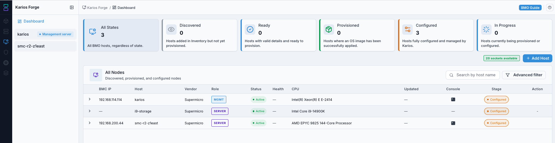
Karios Forge dashboard

Forge dashboard with lifecycle summary and nodes table.

What this screenshot shows:

  • Summary cards for lifecycle visibility: All States, Discovered, Ready, Provisioned, Configured, In Progress

  • Lifecycle filter cards that control table scope

  • Nodes table with key columns (for example BMC IP, Vendor, Stage, Health, Console, Actions)

What you can do from this screen:

  • Select a lifecycle card to filter rows by stage.

  • Open node details from the node row (or eye icon).

  • Open node console from the Console column.

  • Start stage-appropriate action from node details (for example Hardware Reveal) or the available node operation controls.

Expected Outcome:

  • You can identify which lifecycle stage requires action first.

If this fails:

  • Refresh dashboard data and recheck the summary cards.

  • Confirm nodes are visible in Forge and reload the page.

4.2. Use Lifecycle Filters (Cards)

When to Use:

Use this when you need to focus on one lifecycle stage at a time.

Purpose:

Filter the node table to the exact lifecycle stage you want to process.

Steps:

  1. From the dashboard summary cards (shown in 4.1), select one lifecycle card: All, Discovered, Ready, Provisioned, Configured, or In Progress.

  2. Confirm the table now shows only nodes in that stage.

  3. Run the stage-appropriate action for those rows.

Expected Outcome:

  • Table rows match the selected lifecycle filter.

If this fails:

  • Clear and re-apply the filter.

  • Refresh the dashboard and retry.

4.2.1. Use Node Power Action Menu (If Available)

When to Use:

Use this when you need to run node power operations from the node details header.

Purpose:

Run safe power actions for the selected node.

Steps:

  1. Open Forge dashboard and open the target node details page.

  2. In the top-right power/action area, open the Action menu.

  3. Select the required power operation.

  4. Click Execute.

Forge node details showing power action menu

Node details power action menu.

What this screenshot shows:

  • Power status indicator in node details header.

  • Action dropdown with power operations.

  • Execute button to run selected operation.

What you can do from this screen:

  • Select and execute node power operations from the menu.

  • Validate node power behavior during lifecycle operations.

Expected Outcome:

  • Selected power operation is submitted for the node.

If this fails:

  • Refresh node details and retry from the same action menu.

  • Verify BMC connectivity for the target node.

4.2.2. Open Node Console from Dashboard

When to Use:

Use this when you need live boot/output visibility for a node before, during, or after lifecycle actions.

Purpose:

Open node console directly from the Forge dashboard without leaving table workflow.

Steps:

  1. Open Forge dashboard.

  2. Locate the node row in the table.

  3. Click the icon in the Console column.

  4. Observe boot/output state and return to dashboard for the next action.

Expected Outcome:

  • Console session opens for the selected node.

If this fails:

  • Refresh dashboard and retry from the same node row.

4.3. Open Dashboard Help

When to Use:

Use this when you need on-screen guidance for the Forge dashboard controls.

Purpose:

Open dashboard help content and review field/action definitions.

Steps:

  1. Open Control Center -> Forge dashboard.

  2. Click the help icon in the dashboard header.

  3. Review definitions for summary cards, filters, and table actions.

Forge dashboard help panel

Dashboard help view with operational guidance.

What this screenshot shows:

  • Help panel for dashboard cards, filters, and table actions.

  • On-screen definitions tied to dashboard UI elements.

What you can do from this screen:

  • Confirm the meaning of each dashboard card/filter before running lifecycle actions.

  • Validate action labels/intent before selecting row operations.

Expected Outcome:

  • Help content opens and explains dashboard elements before you proceed.

If this fails:

  • Refresh the page and reopen the dashboard.

4.4. BMO Stage Flow from Dashboard

When to Use:

Use this to run the BMO lifecycle in the correct order directly from dashboard stages.

Purpose:

Use the documented BMO lifecycle and map each stage to the dashboard action users should perform next.

Steps:

  1. Start from Discovered nodes.

  2. In the row Action column, click Hardware Reveal.

  3. Monitor until the node moves to Ready.

  4. In the row Action column, click Provision.

  5. Monitor until the node reaches Configured.

Stage

What It Means

Action from Dashboard

Discovered

Server is discovered on network but not yet ready for provision action

Run Hardware Reveal from row Action

Ready

Hardware reveal has completed and server is ready for provisioning

Run Provision from row Action

In Progress

Provisioning or configuration job is currently running

Monitor progress only; do not run concurrent disruptive actions on the same node

Provisioned

Intermediate state where OS image is applied

Continue monitoring and validate progression to Configured

Configured

Node is integrated and production-ready (Ceph storage, SDN network, and configuration applied)

Validate final readiness and proceed with workload onboarding; use Unprovision to return the node to Ready (OS only) or Decommission to fully reset it to Discovered

4.4.1. Move a Node from Discovered to Configured

When to Use:

Use this when a node is visible in Discovered stage and must be moved to production-ready Configured stage.

Purpose:

Use the canonical BMO lifecycle path and confirm the node reaches the expected end state.

Steps:

  1. Confirm the server is present in Discovered with valid BMC details.

  2. Follow 4.4. BMO Stage Flow from Dashboard without skipping stages.

  3. Validate that the node reaches Configured and is ready for workload onboarding.

Expected Outcome:

  • Node reaches Configured stage and is ready for production workloads.

If this fails:

  • Server Not Discovered: verify power, BMC IP reachability, and IPMI port 623 path.

  • Hardware Reveal issue: retry the row Action and monitor status progression.

  • Provisioning start issue: recheck BMC credentials, Device ID, and IPAM prefix.

  • Provisioning completion issue: use node console to identify failed phase and retry only the failed step.

5. Goal 1 - Add a Node Successfully

5.1. Path

Forge -> Add Host -> Add Host form

5.2. Steps

When to Use:

Use this when a node is not yet visible in Forge and must be onboarded manually.

Purpose:

Start host onboarding from Forge and then use the Infrastructure add-host runbook as the canonical form guide.

Steps:

  1. Click Add Host.

  2. Use Add Host (Infrastructure canonical workflow) for the full Details and Review form procedure.

  3. Return to Forge and confirm the node appears in Discovered.

  4. Continue the lifecycle using 4.4. BMO Stage Flow from Dashboard.

5.3. Expected Outcome

  • Node appears in table with Discovered stage and is ready for Hardware Reveal action.

5.4. If this fails

  • Verify BMC IP is reachable

  • Verify username/password

  • Verify BMC network routing/firewall

  • If credentials are wrong, reopen the host entry flow and correct BMC details, then retry onboarding.

6. Goal 2 - Validate BMO Lifecycle Stage

6.1. Stage Map

When to Use:

Use this after opening Forge dashboard and before running stage workflows.

Purpose:

Validate each server is in the correct BMO stage and run the next stage action.

Steps:

  1. Open Control Center -> Forge.

  2. Identify the current stage in summary cards or the node table.

  3. Run only the stage-appropriate action from the dashboard using 4.4. BMO Stage Flow from Dashboard.

Expected Outcome:

If this fails:

  • Recheck current stage and action availability.

  • Confirm no conflicting workflow is already running.

6.2. Stage Checks

When to Use:

Use this when validating a specific stage before taking action.

Purpose:

Prevent wrong-stage actions and ensure the node follows the canonical lifecycle mapping.

Steps:

  1. Identify the node’s current stage in the dashboard card or node table.

  2. Use 4.4. BMO Stage Flow from Dashboard to determine the only valid next action.

  3. Run that action or continue monitoring if the node is already in progress.

Expected Outcome:

  • Each node advances to the next expected stage without skipped prerequisites.

If this fails:

  • Re-run the failed stage action after correcting the root cause.

  • Use node console visibility for boot/progress troubleshooting.

6.3. Provision Inputs and Typical Timing

When to Use:

Use this before clicking Provision or when an operator asks what values and timeframes to expect.

Purpose:

Explain what the Provision action depends on, where node OS images come from, and how long common Forge actions usually take.

Provision input expectations:

  • OS / platform image comes from the environment’s approved bare-metal image catalog or release baseline. This is separate from VM templates and Boot Images used for virtual machines.

  • Storage and resources come from the physical node inventory collected during 9.2. Standard Hardware Reveal Flow (Required in This Guide Path).

  • Network values depend on the site IPAM/prefix assignment and management-network policy used during onboarding.

  • If the UI shows only one node image option, treat it as the site-approved default image for that environment.

  • If no valid image or network choice is available, stop and correct the catalog or site configuration before provisioning.

Typical operator timing guidance:

Action

Typical Time

Notes

Add Host submission

< 1 minute

Form submission is quick; discovery visibility can take slightly longer after refresh.

Hardware Reveal

1-5 minutes

Depends on BMC responsiveness and hardware inventory size.

Provision

5-20 minutes

Depends on image transfer, storage speed, and network reachability.

BIOS apply + reboot

3-10 minutes

Management-node BIOS changes depend on vendor firmware behavior and POST time.

Firmware update

10-30+ minutes

Management-node firmware updates are vendor- and version-dependent; always use a maintenance window.

Hardware inventory refresh

1-3 minutes

Run after reveal, BIOS changes, firmware changes, or hardware changes.

Note

These are operator expectation ranges, not SLA guarantees. Firmware behavior, image download delays, or hardware validation can extend actual runtime.

7. Goal 3 - Review Management Node Details First

7.1. Path

Forge -> Dashboard -> Management server

Quick access:

Forge dashboard -> click the management node

Console quick access:

Forge table -> node row -> Console column icon

Use console when:

  • confirming boot device behavior

  • checking if node is responsive during power operations

7.2. Management Node Completion Check

Complete this check before reviewing server node details. The management node is the control-plane entry in Forge and should be validated first so server-node inventory is interpreted against the correct site and management context.

Steps:

  1. Open the management node from the Forge dashboard or left node list.

  2. Confirm the node is labeled as the management server.

  3. Confirm power state, BMC address, vendor, and health are expected.

  4. Complete the management-node Hardware Inventory, BIOS Config, and Firmware Updates checks below.

  5. Return to the server node only after the management node details are correct.

Expected Outcome:

  • Management node details are reviewed and no unresolved health or identity mismatch remains before server-node inventory validation.

If this fails:

  • Refresh Forge and reopen the management node.

  • Verify BMC connectivity and management-network reachability.

  • Resolve management-node identity or health issues before continuing.

7.3. Management Node Hardware Inventory

When to Use:

Use this after opening the management node details page and before changing BIOS or firmware settings.

Purpose:

Confirm the management node inventory is current before applying configuration or maintenance changes.

Steps:

  1. Open the management node details page.

  2. Open Hardware Inventory.

  3. Click Get latest hardware.

  4. Review device, network, storage, and component information.
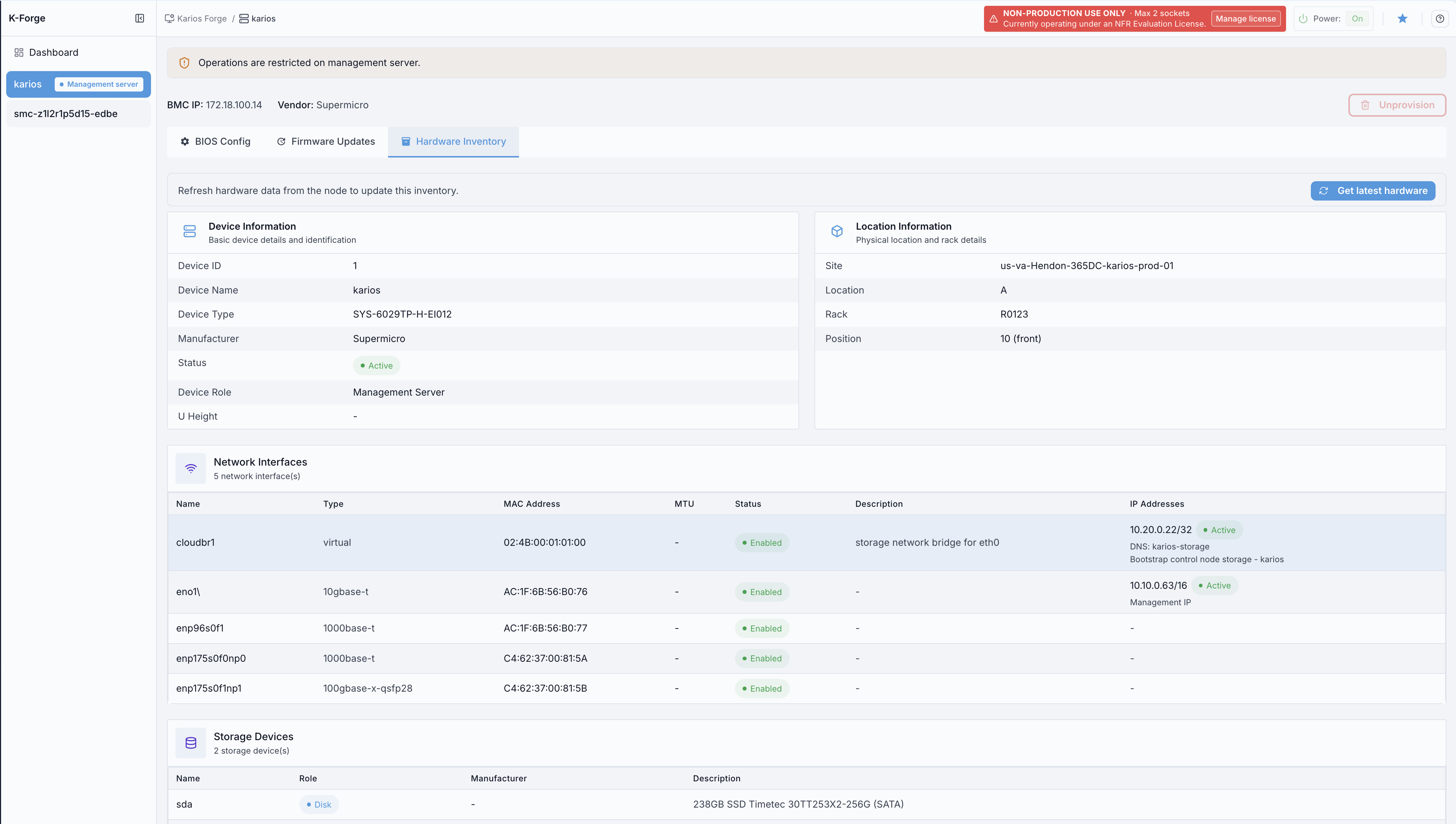
Management node hardware inventory

Management node hardware inventory.

Expected Outcome:

  • Management node inventory is current and matches the expected hardware.

7.4. Management Node BIOS Config

When to Use:

Use this when management-node BIOS values must be reviewed or adjusted before final validation.

Purpose:

Confirm required virtualization and boot-related BIOS values on the management node.

Steps:

  1. Open the management node details page.

  2. Open BIOS Config.

  3. Review summary counts for total, enabled, disabled, and pending BIOS settings.

  4. Review the BIOS Configuration Management panel.

  5. Apply changes only during an approved maintenance window.

  6. Restart the server if BIOS changes require activation.
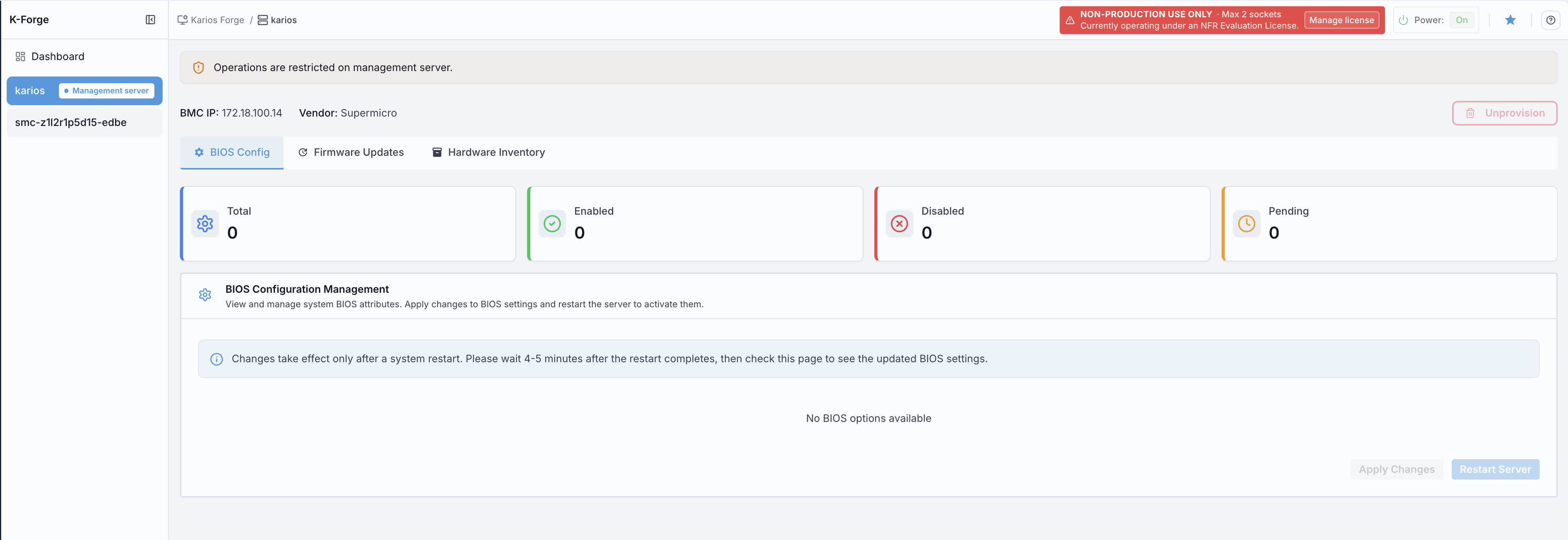
Management node BIOS configuration

Management node BIOS configuration.

Expected Outcome:

  • BIOS values are reviewed, required changes are applied, and the node returns to a stable state after any required reboot.

7.5. Management Node Firmware Updates

When to Use:

Use this when management-node BMC or BIOS firmware must be reviewed or updated.

Purpose:

Confirm current BMC/BIOS firmware versions and apply vendor-approved updates when required.

Steps:

  1. Open the management node details page.

  2. Open Firmware Updates.

  3. Use Firmware Downloads to access the vendor firmware source.

  4. Review current BMC and BIOS firmware model/version values.

  5. Upload only vendor-approved firmware for the exact server model.

  6. Refresh and verify firmware status and audit history after update.
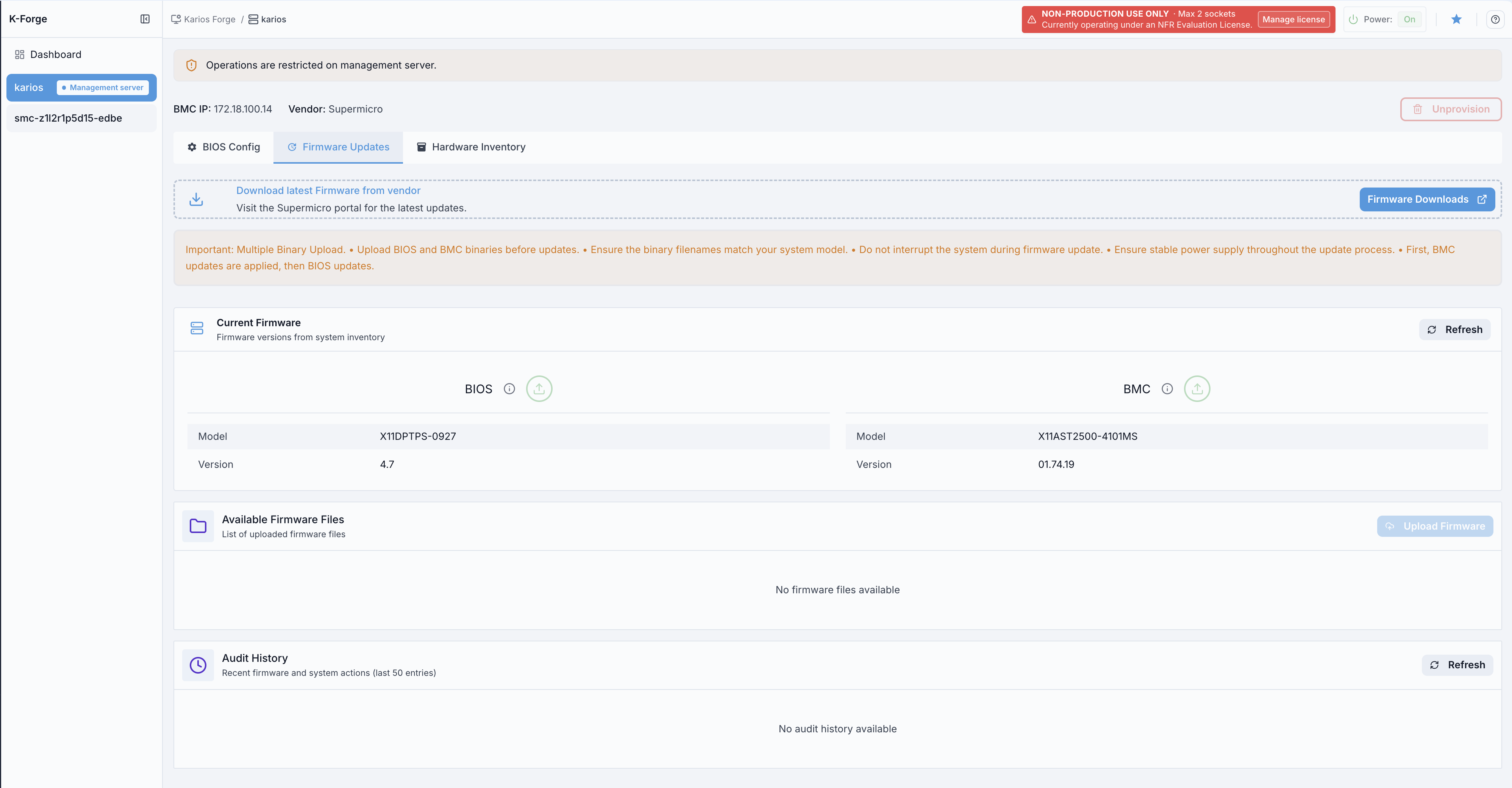
Management node firmware updates

Management node firmware update overview.

Expected Outcome:

  • Firmware versions and health are verified, and any approved update completes successfully before server-node validation continues.

If this fails:

  • Re-check firmware file compatibility with the exact management-node model.

  • Confirm the management node is healthy before retrying the update.

  • Retry only inside an approved maintenance window.

7.6. Management Node Details Actions Reference

Location / Action

What It Does

When To Use

Hardware Inventory -> Get latest hardware

Pulls the latest management-node inventory data.

After reveal, BIOS changes, firmware changes, or physical hardware changes.

BIOS Config -> Apply Changes

Saves selected BIOS values as pending settings.

After approved BIOS value changes.

BIOS Config -> reboot/power action

Restarts the node so BIOS updates take effect.

When the UI indicates a reboot is required.

Firmware Updates -> Refresh

Reloads firmware version and health from the node.

Before and after firmware work.

Firmware Updates -> upload/update

Uploads and applies vendor firmware binaries.

Approved BMC or BIOS firmware maintenance.

8. Goal 4 - Review Server Node Details

8.1. Path

Forge -> Node Details -> Hardware Inventory

Quick access:

Forge dashboard -> click target server node

8.2. Current Server Details Layout

The current server node details page exposes the Hardware Inventory tab only. It does not show separate BIOS Config or Firmware Updates tabs.
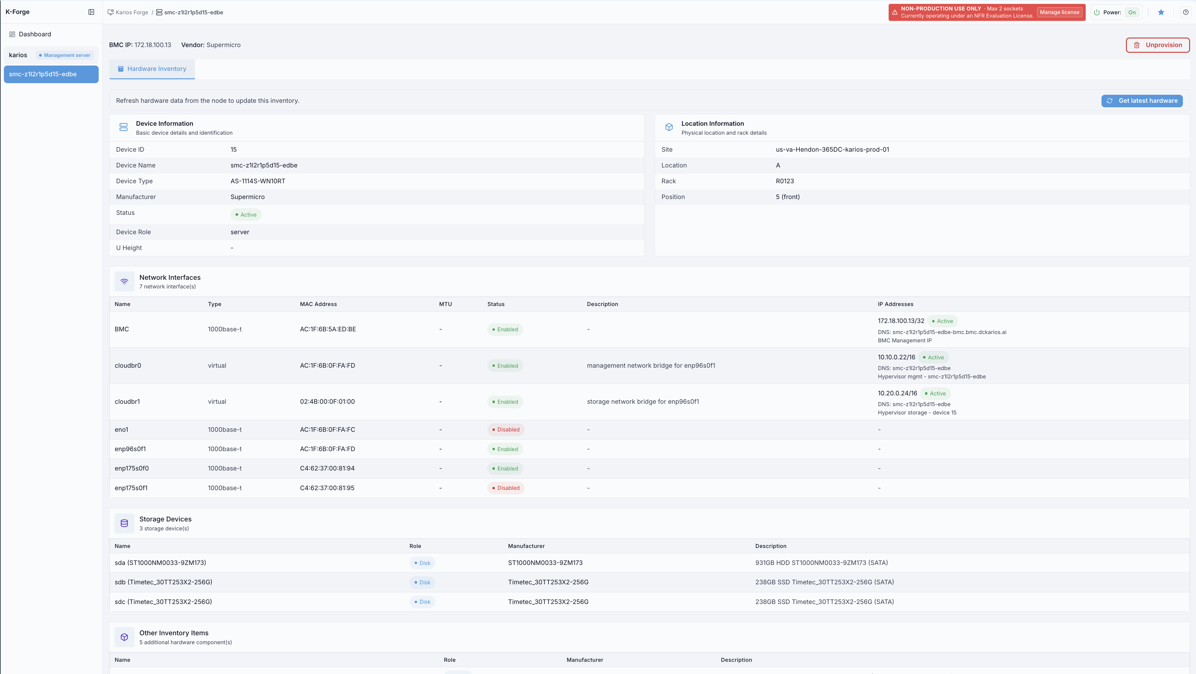
Forge server node details hardware inventory

Server node details with Hardware Inventory selected.

UI components in this screen:

  • Header: node breadcrumb, node name, power state, favorite, and Unprovision

  • Node summary: BMC IP and Vendor

  • Active tab: Hardware Inventory

  • Get latest hardware button: refreshes inventory from the selected node

  • Device Information: device ID, name, type, manufacturer, status, role, and U height

  • Location Information: site, location, rack, and position

  • Network Interfaces: BMC, bridge, and physical interface rows with MAC, status, description, and IP data

  • Storage Devices: discovered disks with role, manufacturer, and description

  • Other Inventory Items: additional discovered hardware components

What this screenshot shows:

  • Server node details currently focus on hardware inventory validation.

  • The available detail tab is Hardware Inventory.

  • The header still provides power state visibility and the Unprovision action, which returns the node to Ready (see 11.6. Unprovision (Reset to Ready)). To fully reset the node to Discovered, use Decommission from the dashboard row Action menu (see 11.1. Decommission a Node (Return to Discovered)).

What you can do from this screen:

Expected Outcome:

  • Node details match the physical server and site inventory records.

If this fails:

  • Refresh node details and click Get latest hardware again.

  • Verify BMC connectivity for the target node.

  • Re-run Hardware Reveal from the dashboard row action if inventory is stale.

8.3. Server Node Details Actions Reference (New User)

Use this section when you are already inside a node details page.

Location / Action

What It Does

When To Use

Expected Result

Dashboard Row -> Action -> Hardware Reveal

Starts hardware reveal for discovered nodes.

Immediately after node enters Discovered stage.

Node transitions to Ready when reveal completes.

Hardware Inventory -> Get latest hardware

Pulls latest inventory data from the node.

After reveal or hardware changes.

Updated component data appears.

Node Details -> Unprovision (header)

Removes only the OS and returns the node to Ready (the inverse of provisioning).

Re-provisioning the OS without a full reset.

Node returns to Ready.

Dashboard Row -> Action -> Decommission

Full reset: removes all configuration and wipes disks.

Resetting or recycling a host completely.

Node returns to Discovered and stays in inventory.

9. Goal 5 - Run Hardware Reveal and Collect Data

9.1. Path

Forge -> Dashboard -> Discovered row -> Action -> Hardware Reveal

Quick access:

Forge table -> node row -> Action -> Hardware Reveal

Forge dashboard showing Hardware Reveal action in discovered rows

Forge dashboard with row Action controls.

What this screenshot shows:

  • Lifecycle cards including Discovered and Ready.

  • Action column in node rows.

  • Hardware Reveal action available for discovered rows.

What you can do from this screen:

  • Select discovered rows and run Hardware Reveal from Action.

  • Monitor stage progression from Discovered to Ready.

9.2. Standard Hardware Reveal Flow (Required in This Guide Path)

When to Use:

Use this after a node appears in Discovered and before running Provision.

Purpose:

Capture hardware facts required for provisioning and move node to Ready.

  1. Filter dashboard to Discovered.

  2. In the node row Action column, click Hardware Reveal.

  3. Monitor operation status and use Console if progress must be validated.

  4. Refresh dashboard and confirm node stage changes to Ready.

Note

Hardware Reveal typically completes in 1-5 minutes. If the node has not reached Ready after roughly 10 minutes, stop waiting passively and use the troubleshooting checks below.

Expected Outcome:

  • Hardware data becomes available for the node.

  • Node stage changes from Discovered to Ready.

If this fails:

  • Retry Hardware Reveal from the row Action button.

  • Verify node health/BMC connectivity.

  • Open the Console column action and verify operation output.

10. Goal 6 - Validate Hardware Inventory

This step must follow the standard Hardware Reveal flow from Section 9.2.

10.1. Path

Control Center -> Forge -> Dashboard -> Select Node -> Hardware Inventory

Quick access:

Forge dashboard -> click target node -> Hardware Inventory

When to Use:

Use this immediately after completing Hardware Reveal or replacing server hardware.

Purpose:

Confirm discovered hardware and network inventory matches the physical server.

Steps:

  1. Open the target node details page.

  2. Click Get latest hardware.

  3. Review device, location, network interface, storage device, and other inventory sections.

Use the server node details screen shown in Section 8.2.

What this screenshot shows:

  • Server node details with the Hardware Inventory tab selected.

  • Hardware sections shown include device information, location information, network interfaces, storage devices, and other inventory items.

  • Node details header actions include Unprovision (returns the node to Ready).

What you can do from this screen:

UI components in this screen:

  • Get latest hardware button: pulls latest inventory from the node

  • Device Information section

  • Location Information section

  • Network interfaces section

  • Storage Devices section

  • Other Inventory Items section

  • Unprovision button in node details header

Hardware Inventory actions (what and why):

  • Get latest hardware: reloads latest inventory data for the node. Why: use after Hardware Reveal or physical hardware changes.

10.2. What to Validate

  • Device identity and vendor are correct

  • Location, rack, and position are correct

  • Network interface details are correct

  • Storage device details are correct

  • Other inventory items are present as expected

Expected Outcome:

  • Inventory matches physical server.

Action checklist on this page:

  1. Click Get latest hardware after Hardware Reveal completes.

  2. Verify timestamp updated.

  3. Review device, location, network interface, storage device, and other inventory sections.

  4. If mismatch is found, return to Hardware Reveal and rerun discovery.

If this fails:

  • Re-run Hardware Reveal

  • Verify the physical device and BMC target are correct

  • Click Get latest hardware again after 5 minutes

11. Goal 7 - Decommission or Unprovision a Node

Forge has two different reset actions. Choose by how far back you want the node to go:

Action

Node ends at

What it does

Decommission (11.1. Decommission a Node (Return to Discovered))

Discovered

Full reset: removes everything added between Discovered and Configured (VMs, SDN network, Ceph storage, IP allocations, OS) and wipes the disks. Run from the dashboard row Action menu.

Unprovision (11.6. Unprovision (Reset to Ready))

Ready

Light reset: removes only the OS installation and returns the node to Ready (the inverse of Provision). Run from the node details header.

11.1. Decommission a Node (Return to Discovered)

When to Use:

Use this when a live Configured compute node must be safely reclaimed and returned to Discovered for later re-provisioning. Decommission keeps the node in inventory; it does not delete it.

Purpose:

Reverse a node’s provisioning in one guided flow: migrate its VMs elsewhere, tear down the SDN overlay, remove Karios storage pools, offboard the node from the Ceph cluster, remove it from the zone, release its IP allocations, reset the OS, and wipe every disk. Only compute nodes can be decommissioned; management nodes cannot.

Before you start:

  1. Back up any data on the node.

  2. Migrate the workloads running on it, or confirm you can lose them.

  3. Confirm an approved maintenance window.

  4. Confirm the cluster keeps at least three healthy compute nodes and that this node is not the only Ceph monitor or manager.

Steps:

The Decommission dialog runs in three phases: Confirm, Preflight, and Progress.

  1. On the Forge dashboard, open the target Configured node’s row Action menu and select Decommission.

  2. Confirm: the Decommission node dialog explains that the node will be returned to Discovered, its VMs and configuration removed, and its disks wiped, and that the node stays in inventory. Nothing changes yet. Click Continue.

  3. Preflight: the dialog runs read-only safety checks and shows the node IP, VM count, decommission targets (where its VMs would migrate), an overall Status (Ready or Confirmation required), the per-check PASS / WARN / FAIL results, and a What will happen step list. See 11.2. Decommission Preflight Checks.

  4. If Status is Confirmation required, read each force-required check, then tick I understand the risks and want to force the decommission only if you accept the stated consequences (forcing overrides a safety check). Use Re-check to re-run preflight after fixing an issue.

  5. Click Decommission to start. The dialog switches to the live Progress view and runs the steps in order (see 11.3. What Decommission Does (Decommission Steps)).

  6. Watch progress to completion. Closing the dialog is safe; the decommission continues in the background and you can reopen it to resume live tracking (see 11.4. Monitor and Resume a Decommission).

Forge dashboard node row Action menu showing the Decommission option

Start Decommission from the node row Action menu.

What this screenshot shows:

  • Forge dashboard nodes table with the lifecycle summary cards.

  • The node row Action menu opened, showing the Decommission option.

What you can do from this screen:

  • Open the Action menu for the target Configured node and select Decommission to open the confirm dialog.

Decommission node confirm dialog

Confirm dialog: what will happen before anything changes.

What this screenshot shows:

  • The Decommission node confirmation: the node returns to Discovered, its VMs and configuration are removed, and its disks are wiped.

  • A note that the node stays in inventory and that a read-only preflight runs first.

What you can do from this screen:

  • Click Continue to run preflight, or Cancel to stop. Nothing changes until you continue.

Expected Outcome:

  • The node completes all decommission steps, its disks are wiped, it powers off, and it returns to Discovered while remaining in inventory.

  • Being powered off in Discovered is expected; the node is powered on again by the next Provision.

  • The completed dashboard is shown at the end of this flow in 11.4. Monitor and Resume a Decommission.

If this fails:

Warning

Decommission is destructive. It permanently removes the node’s OS, configuration, and all disk data, and destroys its VMs if forced without a migration target. Back up data and migrate workloads first, and run it inside an approved maintenance window.

11.2. Decommission Preflight Checks

Preflight runs before any change is made. Checks fall into two classes: hard blocks that cannot be overridden, and force-required checks that can be overridden only by accepting a stated consequence. Warnings never block. When any force-required check is present, the overall Status reads Confirmation required and you must tick the force checkbox to proceed.

Note

In these checks, force means overriding a safety check and accepting its listed consequence. A Ceph monitor and Ceph manager are storage-cluster control roles: if a node runs the only one, removing it can disrupt storage, so keep at least three healthy compute nodes (they also run Ceph) and let those roles move to another node first.

Hard blocks (must be resolved before decommission can start):

Check

Why it blocks

Node state

Node is already Discovered or is not in the Configured state.

Node role

Node is a management node. Only compute nodes can be decommissioned.

Active job

A setup, rollback, or decommission job is genuinely running on the node. A decommission left idle beyond the stale threshold is treated as orphaned, not blocking.

Remaining compute nodes

Other in-flight decommissions would leave fewer than three compute nodes, which is the floor for cluster quorum plus a migration target.

Force-required checks (each has a real consequence if overridden):

Check

Consequence if forced

VM migration

This is the only host running VMs, or the compute manager is unreachable. Forcing destroys the VMs.

Migration capacity

Surviving hosts may not have enough free CPU/RAM for the migrated VMs.

Cluster redundancy

Removing this node’s storage would reduce Ceph data redundancy or risk data loss. Prefer restoring redundancy first.

Monitor quorum

This node runs the only Ceph monitor.

Manager availability

This node runs the only Ceph manager. Forcing can hang the Ceph offboard (see 12.5. Decommission stuck or failed).

System services

This node hosts system VMs (secondary storage, console proxy, or virtual routers). Relocate them first.

BMC reachable

The BMC is unreachable. The decommission steps will run, but the disk wipe needs the BMC and will fail.

Note

Warnings such as agent reachability or wipe-media readiness are informational and do not block the decommission.

Decommission preflight dialog showing node summary and safety checks

Preflight summary and safety checks.

What this screenshot shows:

  • Node summary: node IP, VMs on host, decommission targets (the hosts its VMs would migrate to), and overall Status.

  • The safety-check list with PASS / WARN / FAIL results and a short reason for each (for example cluster_redundancy and system_services).

What you can do from this screen:

  • Read each check to decide whether the node is safe to decommission now, or which issue to fix first.

Decommission preflight step list and force confirmation

Preflight What will happen step list and force confirmation.

What this screenshot shows:

  • The What will happen list of steps the decommission will run.

  • The force-confirmation area with the I understand the risks and want to force the decommission checkbox, and the Re-check and Decommission buttons.

What you can do from this screen:

  • Review the steps, tick the force checkbox only if required, and click Decommission to start, or Re-check to re-run preflight.

11.3. What Decommission Does (Decommission Steps)

Once started, the decommission runs these steps in order. If a step fails, the flow stops at that step and holds the node at Decommissioning so it can be retried from that point; the disk wipe runs only after every step has succeeded.

Note

The preflight What will happen panel previews this sequence. During the run the Progress view shows step X of 12, reaching 12/12 at Remove build ISO; the disk wipe then runs as the final stage and Return node to Discovered completes the run.

#

Step

What it does

1

Migrate VMs off host

Live-migrates VMs to other hosts. Under force with no target, VMs are destroyed.

2

Remove EVPN-VXLAN stack

Gracefully tears down the SDN overlay and frees the VTEP IP.

3

Stop agent services

Stops the Karios agent services on the node.

4

Remove Karios storage pools

Removes the node’s primary storage pools.

5

Prepare Ceph for safe removal

Re-homes data off the node before offboard.

6

Offboard from Ceph

Drains and removes the node from the Ceph cluster.

7

Remove host from zone

Removes the host from the compute zone.

8

Release storage IP

Releases the storage-network IP.

9

Roll back network bridges

Reverts the node’s network bridge configuration.

10

Reset node OS state

Resets the OS (superseded by the disk wipe).

11

Release management IP

Frees the management/OS IP from IPAM (DNS and DHCP).

12

Remove build ISO

Deletes the per-node build ISO.

Wipe

Wipe node disks

Runs only after every step succeeds. Boots a wipe image over the BMC and securely erases every eligible disk. This is the point of no return.

Done

Return node to Discovered

Final state write; the node returns to Discovered and stays in inventory.

11.4. Monitor and Resume a Decommission

When to Use:

Use this to track a running decommission or to recover one that failed or stalled.

Purpose:

A decommission never has to be abandoned. The node is held at Decommissioning until it finishes or you retry, and retry resumes from the step that stopped, not from the beginning. The start control is labeled Decommission on the first run and Retry when you resume a node held at Decommissioning.

Steps:

  1. Reopen the Decommission dialog for the node to live-tail progress, or open it in resume mode from the dashboard.

  2. Read the current status: the running step, the failed step (if any), whether it is recoverable, and the next recommended action shown in the dialog.

  3. Decide whether it is stuck or just in a long step. Ceph rebalance, the disk wipe, and the Ceph offboard each have long waits (see 11.5. Decommission Timing). A job whose timestamp is still advancing is alive, not stuck.

  4. If it failed, fix the root cause named by the failed step, then click Retry. Retry is idempotent: it clears an orphaned job and restarts at the failed step. Re-apply force if a VM-migration or Ceph-redundancy gate still blocks.

Decommissioning node progress view with step counter and audit log

Live progress view with the current step and audit log.

What this screenshot shows:

  • The Decommissioning node progress view: the current step (for example [6/12] Offboarding from Ceph), percent complete, and a live Audit log streaming per-step detail.

  • The counter reaches 12/12 at Remove build ISO, but the run is not done yet: the destructive disk wipe (the point of no return) runs as the final stage after 12/12. Progress continues in the background if you close the dialog.

What you can do from this screen:

  • Follow the current step and audit log, or use Refresh to reload it. During long steps (such as the Ceph offboard) confirm the job is still advancing.

Expected Outcome:

  • The decommission resumes from the failed step and runs to completion, or the dialog reports the specific check to fix.

  • On success, the Progress view reaches the final stage, the audit log ends with Return node to Discovered, and the node’s dashboard state changes to Discovered.

Forge dashboard showing the decommissioned node back in the Discovered stage

After decommission: the node is back in the Discovered stage and still listed.

What this screenshot shows:

  • The Forge dashboard after decommission: the Discovered summary card count increases and the node’s row Stage reads Discovered.

  • The node remains in the nodes table — it stays in inventory and is not deleted.

What you can do from this screen:

If this fails:

11.5. Decommission Timing

These are operator expectation ranges, not guarantees.

Wait

Typical Time

Notes

Node comes up into wipe image

5 minutes

If exceeded, the BMC boot override likely did not apply; verify BMC reachability (see 12.2. Power actions fail).

Disk wipe (wait for power-off)

up to 10 minutes

The node powers off only when every disk verifies clean.

Ceph rebalance wait

up to 30 minutes

Data re-homes before the node’s storage is removed.

Ceph offboard job

up to 60 minutes

Full drain and removal from the Ceph cluster.

Stale-decommission (orphan) threshold

35 minutes

A job idle longer than this is treated as orphaned and can be retried.

11.6. Unprovision (Reset to Ready)

When to Use:

Use this when you only need to remove the OS from a node and return it to Ready so it can be re-provisioned. Unprovision is the inverse of Provision (it undoes the OS install). This is the opposite of 11.1. Decommission a Node (Return to Discovered), which fully resets the node to Discovered.

Purpose:

Remove only the OS installation and move the node back to Ready. Ceph storage, the SDN network, and the rest of the configuration are applied later by the Configure step, so they are not involved in this action.

Path:

Forge -> Node details -> top-right Unprovision button

Before you start:

  1. Back up any data and migrate workloads that depend on the current OS.

  2. Confirm an approved maintenance window.

Steps:

  1. Open the node details page and click Unprovision in the top-right header.

  2. Confirm in the dialog.

Expected Outcome:

Warning

Unprovision is destructive for the OS and any workload state on the node. Use 11.1. Decommission a Node (Return to Discovered) for a full reset to Discovered.

If this fails:

  • Verify the node is reachable in the BMC console.

  • Reopen node details and retry Unprovision.

  • Confirm no conflicting workflow is currently running on the node.

12. Quick Troubleshooting by Outcome

12.1. Node cannot be added

  • Check BMC IP reachability

  • Check BMC credentials

  • Check management VLAN/firewall

12.2. Power actions fail

  • Validate BMC login directly

  • Retry after session refresh

  • Verify node/BMC is not in error state

  • Open node console from the Console column icon to verify host responsiveness

12.3. Reveal has no data

  • Re-run Hardware Reveal from the row Action button

  • Verify node is in Discovered before retry

  • Use the console icon to confirm action progress/output

  • Refresh dashboard and confirm stage transition

12.4. Inventory incomplete

  • Re-run reveal

  • Verify the node details page points to the expected server

  • Click Get latest hardware and wait for refresh completion

12.5. Decommission stuck or failed

The node is held at Decommissioning on any failure so it can be retried; retry resumes from the failed step. Match the symptom below, fix the cause, then retry (see 11.4. Monitor and Resume a Decommission).

Where it stops

Likely cause

Fix

Migrate VMs off host

No migration target or not enough capacity

Free capacity on another host, or force (destroys the VMs), then retry.

Offboard from Ceph, hangs ~35 min

Node runs the only Ceph manager, which was drained

Restore a manager on another host, confirm Ceph responds, then retry.

Offboard from Ceph, fails fast

Ceph health, replica-safety, or rebalance gate

Fix Ceph health or add storage capacity, then retry.

Wipe node disks, skipped

An earlier decommission step failed

Fix that step and retry; the wipe runs only after every step succeeds.

Wipe node disks, never powers off

A disk did not verify clean (for example a locked SED or remote LUN)

Inspect the wipe console, resolve the device, then retry.

Nothing happens at the start

Preflight hard block, or a force-required check needs force

See 11.2. Decommission Preflight Checks.

Note

Do not decommission the node that runs the only Ceph manager or monitor. Keep at least three healthy compute nodes (they also run Ceph) and let those roles relocate first. Forcing past the manager-availability check can hang the Ceph offboard until its deadline.

13. Quick Action Map

  • Add host: Forge -> Add Host

  • Open node: Forge -> click node

  • Stage check: Forge -> Discovered card/filter -> run Hardware Reveal (Action)

  • Provision node: Forge dashboard -> Ready row -> Action -> Provision

  • Ready-to-provision path: Discovered -> Hardware Reveal (Action) -> Ready -> Provision (Action)

  • Open console: Forge table -> Console column icon

  • Reveal: Forge table -> node row -> Action -> Hardware Reveal

  • Inventory: Node details -> Hardware Inventory

  • Unprovision (reset to Ready): Node details -> Unprovision (top-right header)

  • Decommission (reset to Discovered): Dashboard row -> Action -> Decommission (Confirm -> Preflight -> Progress)

  • Resume decommission: Dashboard row -> Action -> Decommission -> Retry

14. New User Journey (First Operational Run)

Use this checklist for your first node from start to configured-and-validated state.

14.1. First Run Sequence

  1. Open Forge and filter Discovered.

  2. If node is missing, use Add Host to add host with BMC details.

  3. Run Hardware Reveal from row Action and confirm stage becomes Ready.

  4. In node row Action, run Provision.

  5. Wait and confirm node appears in Configured.

  6. Open and complete the management node details checks from Sections 7.2 through 7.5.

  7. Open the server node details page from Section 8.2.

  8. Run required validation checks:

  • run standard Hardware Reveal flow from Section 9.2

  • validate Hardware Inventory in Section 10

  1. Open the Console column icon and verify node boot/output health.

  2. Confirm health is green and inventory matches hardware.

14.2. Done Criteria (New User Success)

A node is ready for normal operations when all are true:

  • Stage is Configured

  • Health is green/OK

  • Hardware Reveal completed successfully

  • Hardware Inventory matches expected components

To reset a node later, use 11.6. Unprovision (Reset to Ready) to remove only the OS and return it to Ready, or 11.1. Decommission a Node (Return to Discovered) to fully reset it to Discovered.


→ Next: Network