Compute - Virtual Machines
See also
Prerequisites for VM operations:
Infrastructure for healthy zone/pod/cluster/host
Instance Profiles for CPU/RAM sizing
Network for optional custom network design
Note
In the current Compute section, Virtual Machines and Auto Scaling
workflows are covered in this guide.
Warning
Live VM migration is not currently supported as a standard platform feature. Plan workload movement using controlled stop/start or cutover workflows.
Before You Begin - Prerequisites and Readiness Validation
This section validates all prerequisites before creating your first VM. Complete this checklist to ensure smooth VM provisioning.
See also
Cross-check related setup guides:
Getting Started for installation media and onboarding baseline
Infrastructure for zone/pod/cluster/host readiness
Network for optional custom network design (not required for first VM in standard setup)
Compute Policies for compute/disk profiles and access options
Storage for VM templates and boot images
Important
Seeing 0 VMs after initial Karios deployment is expected. Internal system VMs are not shown in the user VM dashboard.
Important
Live VM migration is not currently supported as a standard Karios platform feature. Plan maintenance and host recovery with controlled stop/start, reboot, HA restart behavior, or workload cutover workflows instead.
New-User Flow at a Glance
Use this simple sequence for first success:
Validate prerequisites (instance profile, host up, VM template/boot image ready, instance storage up).
Open
Virtual Machinesand clickCreate VM.Choose
VM TemplateorBoot Imagebased on your requirement.Track VM state until
Running.Open VM details and validate
Details,Console,Metrics, andKarios Shield.Take a snapshot before high-risk changes.
Use lifecycle actions (start/stop/reboot/delete) only after impact check.
Mandatory Requirements for VM Creation
Use this as the minimum go/no-go check before opening Create VM.
Required item |
Minimum state |
UI path |
Action if missing |
|---|---|---|---|
VM permissions |
|
|
Request VM access from an administrator before continuing. |
Instance profile |
At least one enabled profile |
|
Click |
Host capacity |
At least one host in |
|
Onboard or repair a host until at least one host is |
Instance Storage |
At least one storage pool in |
|
Add or repair an instance storage pool and confirm free capacity. |
VM image |
At least one VM template or boot image in |
|
Register a VM template or upload a boot image, then wait for |
Guest network |
At least one usable guest network |
|
Use the default Bootstrap guest network or create/repair a guest network before provisioning. |
Note
For first-VM workflows in standard Bootstrap deployments, the default guest network is usually sufficient.
Quick Setup Path for Missing Prerequisites
Follow this order when one or more required items are missing:
Open
Compute Policies -> Instance Profilesand create one enabled instance profile.Open
Infrastructure -> Hostsand confirm at least one host isUp.Open
Storage -> Instance Storageand confirm at least one pool isUpwith enough free capacity.Open
Storage -> VM TemplatesorStorage -> Boot Imagesand make sure at least one image isReady.Confirm a guest network is available, either from Bootstrap defaults or in
Network -> Guest Networks.Return to
Compute -> Virtual Machinesand clickCreate VM.
Quick Start Validation
For experienced users, confirm these four items:
[ ] At least one instance profile exists
[ ] At least one host is
Up[ ] At least one VM template
ReadyOR boot image uploaded[ ] Instance Storage shows
Upstate
Simple check steps:
Step 1 - Instance profile
Go to: Compute Policies -> Instance Profiles
What to confirm:
At least one row exists in the table.
Profile is enabled/active.
CPU and RAM values are visible (example: 1 CPU, 1 GB RAM).
Quick fix if missing:
Click
+ Create.Set a name (example:
small-1c-1g).Set CPU/RAM (minimum test profile:
1 CPU,1024 MB).Save and confirm the profile appears enabled.
Full guide: Instance Profiles
Step 2 - Host availability
Go to: Infrastructure -> Hosts
What to confirm:
At least one host row exists.
Host state is
Up(notErrororDisconnected).Host has available CPU and memory.
Quick fix if missing:
Add/onboard a host through infrastructure workflow.
Resolve host connectivity/BMC issues until at least one host is
Up.Recheck host resource availability.
Full guide: Infrastructure
Step 3 - VM Template or Boot Image
Go to: Storage -> VM Templates or Storage -> Boot Images
What to confirm:
At least one image status is
Ready.Image is available in the zone where you will deploy the VM.
OS type matches your first workload.
Quick fix if missing:
Fast path: register/select a VM template and confirm
Readystatus.Alternative: upload a boot image and use boot-image provisioning (longer path).
Reopen the table and confirm
Readybefore starting VM creation.
Full guides: VM Templates, Boot Images
Step 4 - Instance Storage
Go to: Storage -> Instance Storage
What to confirm:
At least one storage pool row exists.
Pool state is
Up.Free capacity is sufficient for planned VM size.
Quick fix if missing:
If no pool exists, click
+ Add Storage Pooland complete required fields.If pool exists but is not
Up, verify storage endpoint/network path and refresh state.Continue only when at least one pool is
Up.
Full guide: Instance Storage
Note
Manual networking configuration is not required for initial VM creation in standard Bootstrap deployments. Use Network docs when you need custom VLAN/CIDR/public segmentation.
If all four are checked, skip to Section 2 (Navigating the VM Dashboard).
If any are unchecked, continue with detailed validation below.
Detailed Prerequisites Validation
Use this section only if the 4 quick checks above pass but VM provisioning is still blocked.
Access Checks
Path: User Icon -> My Profile
Confirm:
Your role includes
VM_VIEWandVM_MANAGE.You can see the VM menu and
Create VMbutton in VM dashboard.
If not met:
Permission issue: request VM Admin or higher role from your administrator.
Host and Capacity Checks
Path: Infrastructure -> Hosts and Storage -> Instance Storage
Confirm:
At least one host is
Up(notError/Disconnected).At least one instance storage pool is
Up.Instance Storage has enough free capacity for planned VM size.
If not met:
Add/repair hosts in Infrastructure.
Add/repair storage in Instance Storage.
Image Path Checks
Path: Storage -> VM Templates / Storage -> Boot Images and Storage -> Image Storage
Confirm:
At least one VM template or boot image is
Ready.Image Storage is healthy when using templates or boot images.
Image is available in the target deployment zone.
If not met:
Register VM template: VM Templates
Upload boot image: Boot Images
Fix image-store issues: Image Storage
Optional Security Check
Path: Compute Policies -> SSH Keypairs
Optional: at least one keypair is present for secure Linux access.
If missing, create one in SSH Keypairs.
Final Preflight Checklist
Run this final preflight before clicking Create VM and before final submission with Provision VM:
[ ] VM_MANAGE permission present
[ ] One host Up
[ ] One instance storage pool Up
[ ] One instance profile enabled
[ ] One VM template or boot image Ready
Common Missing-Prerequisite Symptoms
Symptom |
Likely Missing Prerequisite |
|---|---|
Create VM panel has empty dropdowns |
Instance profile or VM template/boot image missing |
|
Host offline, insufficient resources, or storage full |
VM stuck in |
Storage issue or platform initialization delay |
VM has no IP address |
Network not in |
Cannot select VM template |
Image Storage unavailable or VM template not |
If You See Any Empty Dropdowns
Warning
If any dropdown in the Create VM panel is empty, that prerequisite is missing.
Troubleshooting:
Empty
Instance Profile-> Create profile: Instance ProfilesEmpty
VM Template-> Register VM template: VM TemplatesEmpty
Boot Image-> Upload boot image: Boot Images
Manual network creation is optional for first VM in standard setup.
Note
If all prerequisites are met, continue to Section 2. Navigating the VM Dashboard to validate dashboard access and filters, then continue to Section 3. Creating Your First Virtual Machine.
Tip
Bookmark this checklist for future VM deployments or troubleshooting.
2. Navigating the VM Dashboard
Path: Control Center -> Compute -> Virtual Machines
Note
In the current Compute menu, Virtual Machines is the workflow covered
in this guide.
When to Use:
Use this page first whenever you need to create, locate, or troubleshoot a virtual machine.
Purpose:
Understand the VM cards, filters, and action entry points before performing lifecycle actions.
Steps:
Open
Control Center -> Compute -> Virtual Machines.Review summary cards and active filters.
Confirm you can access VM rows and the
Create VMbutton.
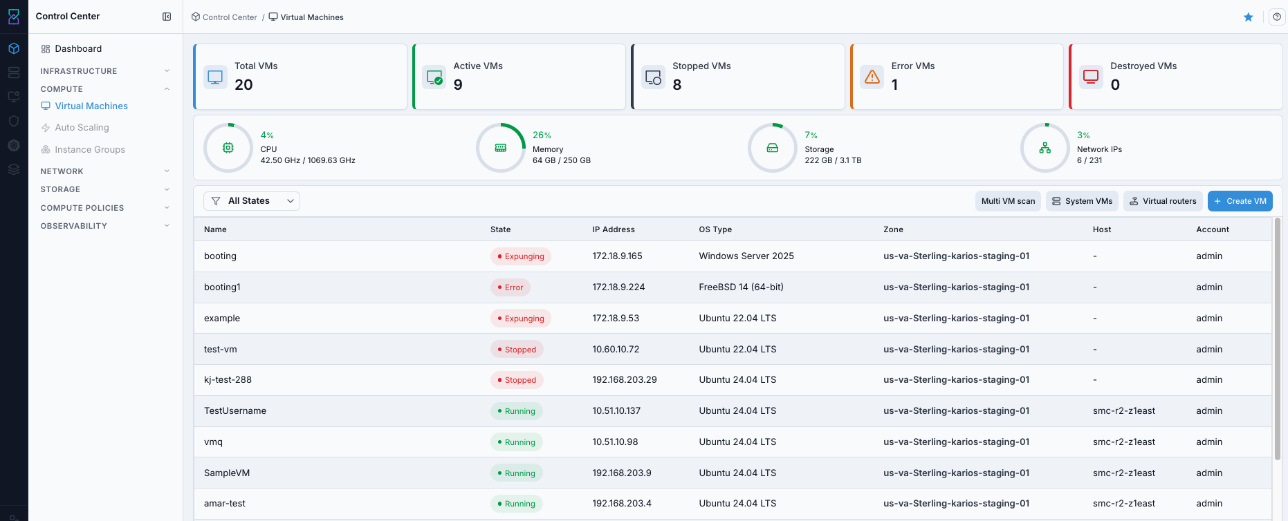
VM dashboard with summary cards and VM list.
What this screenshot shows:
Summary cards:
Total VMs,Active VMs,Stopped VMs,Error VMs, andDestroyed VMsGlobal filters for state, zone, host, and memory
Create VMbutton,System VMsandVirtual routersquick actions, and VM inventory table
Expected Outcome:
You can see VM counts, VM list, and action entry points.
If this fails:
Confirm the VM is in the required power state for snapshot creation and refresh the
Snapshottab before retrying.Verify the selected volume is still attached, supports snapshots, and has enough backend capacity for the new restore point.
Check Observability Events/Alerts for the VM name, target volume, and action timestamp, then retry after correction.
2.1. Dashboard Summary Cards
Card |
Description |
|---|---|
Total VMs |
Total number of virtual machines visible in your environment. |
Active VMs |
VMs currently running and available for workload use. |
Stopped VMs |
VMs currently powered off. |
Error VMs |
VMs in error/expunging or other non-healthy state that require intervention. |
Inactive VMs |
VMs that are not currently running (for example stopped/non-running states). |
Destroyed VMs |
VMs deleted or currently in destroyed lifecycle state. |
2.2. VM Table Columns
Column |
Description |
|---|---|
Name |
VM identifier. Click to open VM details. |
State |
Current lifecycle state (for example |
IP Address |
Primary VM IP. |
Architecture |
CPU architecture associated with the VM image/hypervisor path. |
Host |
Physical host or cluster where the VM is currently placed. |
Account |
Account/owner associated with the VM. |
Zone |
Zone in which the VM is deployed. |
Tip
Host can show - for stopped/error/destroyed VMs.
2.3. State Filters
Use the state filter control to narrow VM list by runtime state.
Active: shows running VMs.Inactive: shows VMs that are stopped or otherwise non-running.All States: shows full inventory including running and non-running VMs.Use these filters first before manual scanning when the VM list is large.
2.4. Quick Actions and Navigation
Click VM
Nameto open the VM detail page.Hover a VM row to expose quick actions.
Use the row
Actionsmenu (⋮) for additional actions available for current VM state.Use detail page tabs (Details, Console, Snapshot, Volumes, Metrics, Karios Shield) for deeper operations.
Use top-right dashboard quick actions for platform VM views:
System VMsandVirtual routers.
2.4.1. View System VMs
Open
Compute -> Virtual Machines.Click
System VMsnear theCreate VMbutton.Review system VM rows (console proxy, Image Storage VM/SSVM, and status).
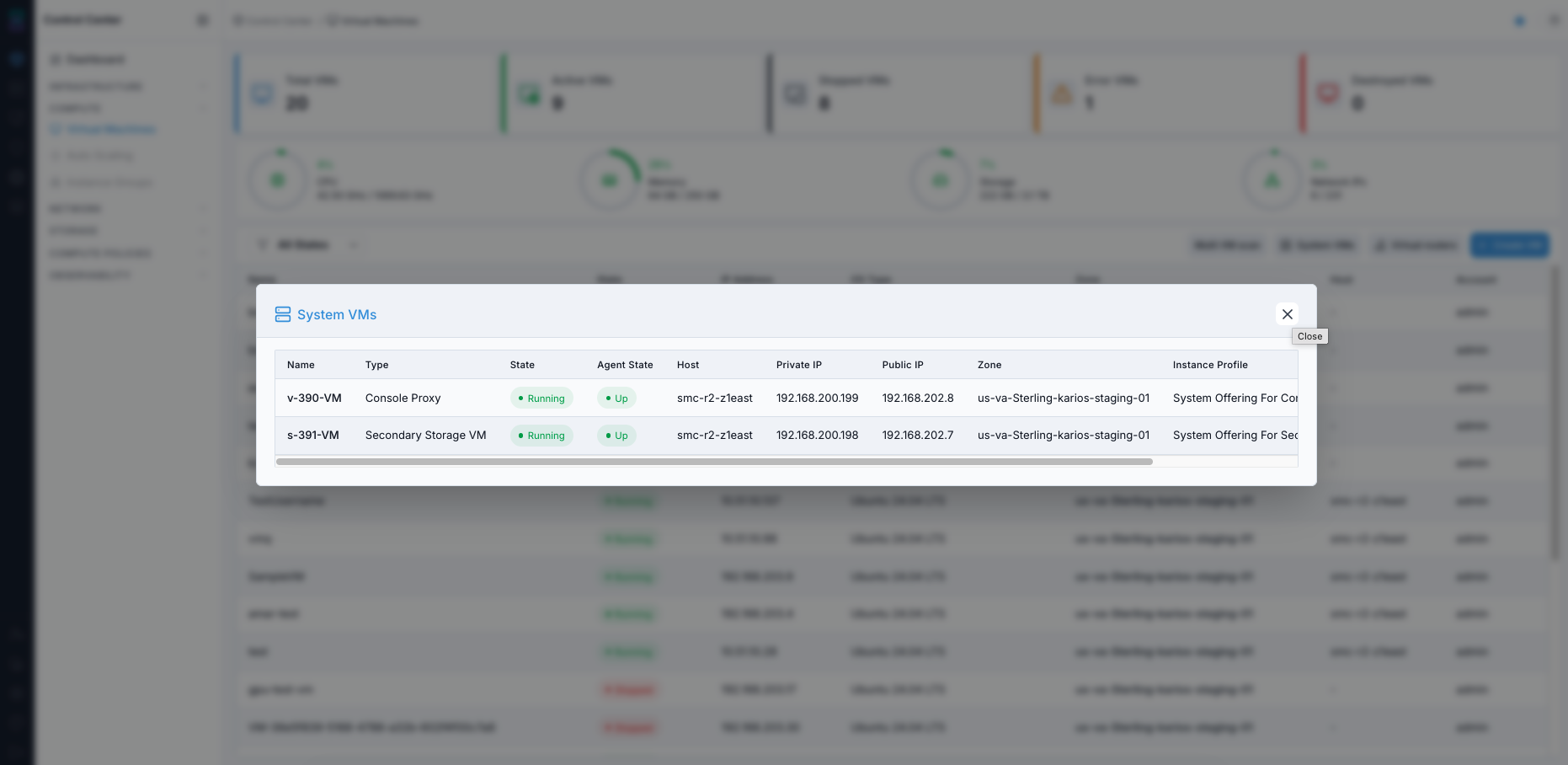
System VMs modal opened from the VM dashboard.
Expected Outcome:
You can verify internal system VM health and placement.
2.4.2. View Virtual Routers
Open
Compute -> Virtual Machines.Click
Virtual routersnear theCreate VMbutton.Review router state, guest/public IP, zone, and host placement.
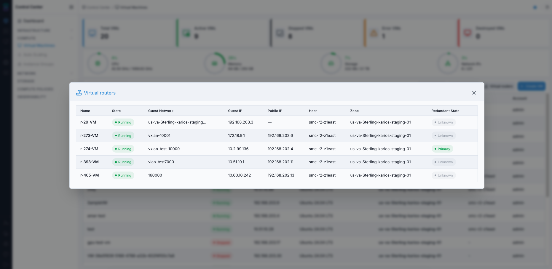
Virtual routers modal opened from the VM dashboard.
Expected Outcome:
You can inspect virtual router inventory and runtime status.
Tip
If a VM is not visible as expected, use the All States filter and narrow by state.
2.5. Operator Tips (New User)
Use state and zone filters to reduce investigation effort.
Use
IP Addressfor quick SSH/RDP targeting during validation.Use
Hostto understand VM placement and basic distribution across infrastructure.For long lists, use browser find (
Ctrl+F/Cmd+F) by VM name or IP.Start/stop VMs based on active workload need to optimize compute usage.
2.6. Open Dashboard Help Panel
Click the help icon (
?) in the top-right corner of the dashboard.Use search in the help panel to find section-specific guidance.
Close the panel after review.
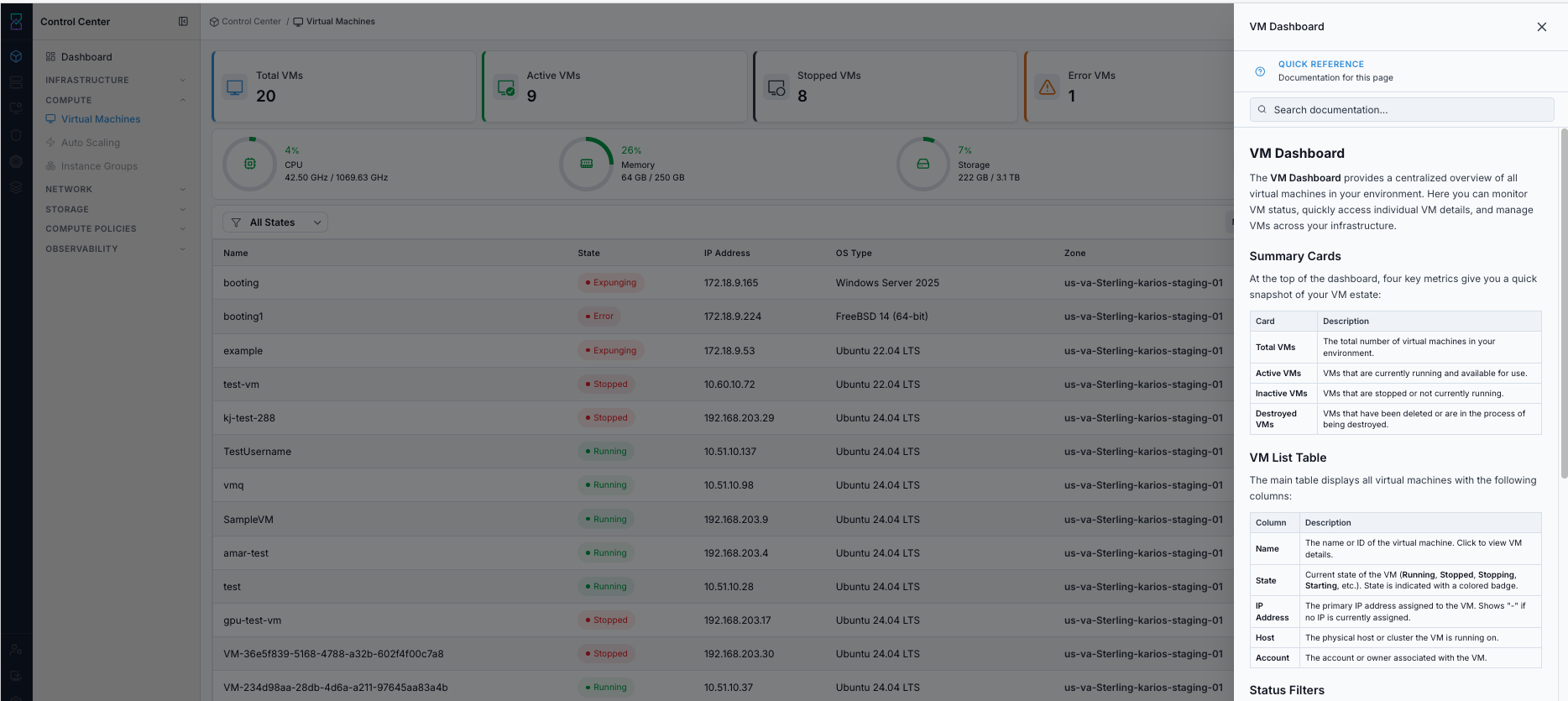
In-app help panel for the VM Dashboard page.
Expected Outcome:
You can access in-context guidance without leaving the VM dashboard.
2.7. Dashboard Validation Checkpoint
When to Use:
Run this quick checkpoint after opening the VM dashboard and before starting VM provisioning.
Purpose:
Confirm that the VM dashboard is accessible and ready for create/operate workflows.
Steps:
Confirm the
Create VMbutton is visible and clickable.Confirm at least one VM row is visible (or expected empty state is shown without errors).
Confirm state filters work (for example
ActiveandAll States).Confirm quick actions
System VMsandVirtual routersopen successfully.
Expected Outcome:
Dashboard navigation and controls are validated for VM provisioning.
If this fails:
Confirm the target snapshot still exists for the correct VM volume and that the VM is in the required state for restore.
Validate the rollback target carefully and ensure no newer guest changes are still expected to be preserved.
Check Observability Events/Alerts for the VM name, snapshot name, and restore timestamp, then retry after correction.
Note
Proceed to Section 3. Creating Your First Virtual Machine to launch the Create VM flow (panel title Provision Virtual Machine).
3. Creating Your First Virtual Machine
3.1. Launch the Create VM Panel
When to Use:
Start here when prerequisites are complete and you are ready to provision a VM.
Purpose:
Open the Create VM flow and confirm the Provision Virtual Machine panel loads with the required fields.
Steps:
Open VM dashboard.
Click
Create VMat top-right.Confirm the
Provision Virtual Machinepanel opens.
Expected Outcome:
The
Provision Virtual Machinepanel opened fromCreate VMis visible and ready for input.
If this fails:
Refresh the VM dashboard and confirm the
Create VMbutton is visible and enabled in the current account/project scope.Recheck the VM creation prerequisites above, especially instance profile, host, Instance Storage, and image readiness.
Check Observability Events/Alerts for create-form or permission errors before retrying.
Creation Form Views (UI Reference)
Use these two form views before filling fields:

Create VM panel - VM Template path.
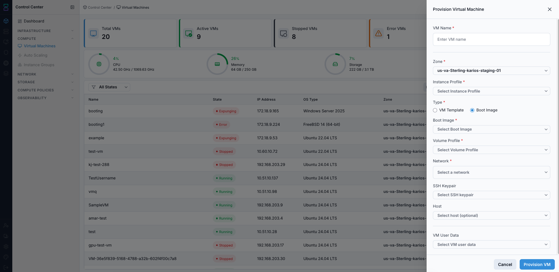
Create VM panel - Boot Image path.
3.2. Common Fields (VM Template and Boot Image)
Field |
Required |
Visible When |
Description |
|---|---|---|---|
VM Name |
Yes |
Always |
VM identifier used in dashboard and operations. |
Zone |
Yes |
Always |
Deployment zone for compute/network/storage placement. |
Instance Profile |
Yes |
Always |
Compute sizing profile (CPU and memory). |
Type |
Yes |
Always |
Creation source selection: |
VM Template |
Yes |
Type = |
Prebuilt VM image used for fast provisioning. |
Boot Image |
Yes |
Type = |
Installer media used for manual OS installation. |
Volume Profile |
Yes |
VM Template and Boot Image |
Primary disk performance/size profile. |
Network |
No |
VM Template and Boot Image |
Guest network attachment for VM connectivity. |
SSH Keypair |
No |
VM Template and Boot Image |
Key-based access bootstrap for Linux VMs. |
VM User Data |
No |
VM template workflow () |
First-boot automation script/cloud-init configuration. |
Field Tips (New User)
VM Name: use descriptive names such asweb-prod-01ordev-api-01.Zone: choose based on locality/compliance and available capacity.Instance Profile: align with workload demand; over-sizing wastes capacity.Volume Profile: choose performance tier based on I/O needs.Network: optional for first VM in standard setup; keep default unless custom network behavior is required.SSH Keypair: keep private key secure; key loss can block access.VM User Data: use for repeatable first-boot setup; test scripts before production.
Submission Actions
Cancel: closes dialog with no resource allocation.Provision VM: starts provisioning and returns to VM list for status tracking.
Expected Outcome:
VM appears in dashboard and transitions through
Starting/CreatingtoRunning(orErrorif prerequisites fail).
3.3. Type Selection - How Form Changes
VM Template: preconfigured OS image path.Boot Image: installer-based path for custom OS setup through Console.
3.4. VM Template vs Boot Image (Quick Comparison)
Attribute |
VM Template |
Boot Image |
|---|---|---|
Boot readiness |
Boots directly to installed OS. |
Boots installer media; manual OS install required. |
Best for |
New users and standardized deployments. |
Custom installs and advanced use. |
Unique field |
VM User Data |
Boot image selection |
3.4.1. Decision Gate (What to choose now)
If a VM template is available and in
Readystate: use VM Template path.If a VM template is unavailable but a boot image is ready: use Boot Image path and complete OS install in Console.
If neither is available: stop and complete media prerequisites first.
3.5. Step-by-Step (VM Template Path)
When to Use:
Use this path for provisioning with prebuilt operating system images.
Purpose:
Deploy a VM that can reach Running quickly with minimal manual setup.
Steps:
Click
Create VM.Enter VM Name.
Select Zone.
Select Instance Profile.
Keep Type as
VM Template.Select VM Template.
Select Volume Profile.
Optional: Select Network if required for your deployment.
Optional: SSH Keypair.
Optional: VM User Data.
Click
Provision VM.Confirm state becomes
Running.
Expected Outcome:
VM reaches
Runningstate.Newly created VM appears automatically in the VM dashboard list.
Post-provision state handling:
Starting/Creating: monitor state transition.Running: proceed to validation and access.Error: check host/storage/platform state and active alerts.If VM is not visible in the current view, clear filters or switch
All Statesselection.
If this fails:
Confirm the target snapshot still exists for the correct VM volume and that the VM is in the required state for restore.
Validate the rollback target carefully and ensure no newer guest changes are still expected to be preserved.
Check Observability Events/Alerts for the VM name, snapshot name, and restore timestamp, then retry after correction.
3.6. Step-by-Step (Boot Image Path)
When to Use:
Use this path when you must install the guest OS manually from installer media.
Purpose:
Provision a VM and complete operating system installation through Console.
Steps:
Click
Create VM.Enter VM Name.
Select Zone.
Select Instance Profile.
Set Type to
Boot Image.Select Boot Image.
Select Volume Profile.
Optional: Select Network if required for your deployment.
Optional: SSH Keypair.
Optional: VM User Data.
Click
Provision VM.Open Console and complete OS installation.
Expected Outcome:
VM is provisioned and boots the boot image installer; OS setup must be completed in Console.
Newly created VM appears automatically in the VM dashboard list.
Post-provision state handling:
Starting/Creating: monitor state transition.Running: open Console to run installer.Error: validate boot-image/media/zone selections (and custom network selection if used), then check active alerts.If VM is not visible in the current view, clear filters or switch
All Statesselection.
Warning
Boot-image VM is not ready for application use until OS installation is finished in Console.
If this fails:
Confirm the VM is in the required power state for snapshot creation and refresh the
Snapshottab before retrying.Verify the selected volume is still attached, supports snapshots, and has enough backend capacity for the new restore point.
Check Observability Events/Alerts for the VM name, target volume, and action timestamp, then retry after correction.
4. Managing VM Lifecycle (Start, Stop, Reboot, Delete)
VM actions are available from the VM detail page action toolbar and state-aware action dialogs.
When to Use:
Use this section whenever you need to change VM power state, decommission a VM, or resize compute profile.
Purpose:
Perform lifecycle actions safely with state checks and impact awareness.
Steps:
Open
Virtual Machinesand click the target VM name.Confirm the current VM state in the header.
Click the required action icon (Start, Stop, Reboot, Delete, or Scale Instance).
Confirm the action dialog.
Watch state transition until the VM returns to a stable state.
Note
Common actions are shown as icon buttons in the VM details header.
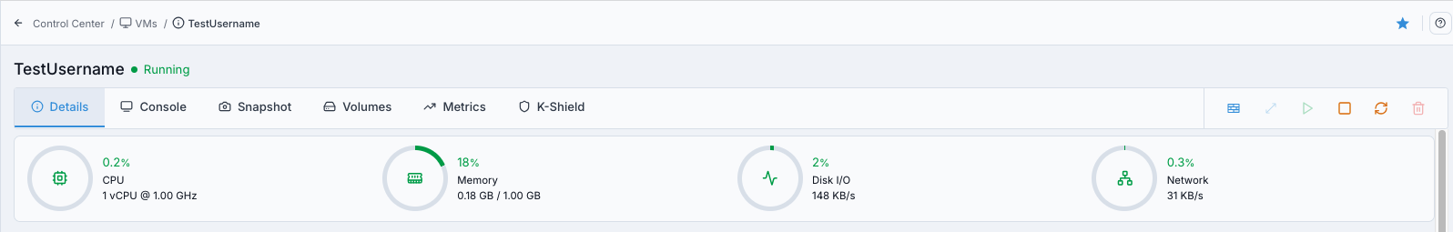
VM header action toolbar.
What this screenshot shows:
Action icons for scaling, start, stop, reboot, delete, and recovery/state operations
Icon availability reflects current VM state
Icon-only action tip:
Hover each icon and confirm tooltip text before clicking (for example
Start,Stop,Reboot,Delete,Scale Instance).
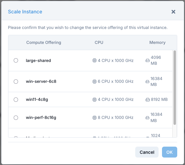
Scale Instance dialog.
What this screenshot shows:
Instance profile options with CPU and memory values
OKconfirmation action to apply sizing change
Action |
What It Does |
When To Use |
|---|---|---|
Start |
Powers on stopped VM. |
Resume service. |
Stop |
Graceful shutdown, keeps config/disks. |
Maintenance or planned pause. |
Reboot |
Graceful reboot. |
Apply config/package updates. |
Delete / Destroy |
Moves VM to destroyed state. |
Decommission VM. |
Scale Instance |
Changes VM instance profile (CPU/memory profile). |
Right-size VM after performance review. |
Warning
Delete/Destroy is destructive. Confirm backup or snapshot coverage before proceeding.
Warning
Recoverability after delete depends on platform expunge/retention policy and can not be guaranteed.
Expected Outcome:
VM state or VM sizing changes according to selected action.
If this fails:
Confirm the target snapshot still exists for the correct VM volume and that the VM is in the required state for restore.
Validate the rollback target carefully and ensure no newer guest changes are still expected to be preserved.
Check Observability Events/Alerts for the VM name, snapshot name, and restore timestamp, then retry after correction.
5. Running and Non-Running States
When to Use:
Use this view when you need to quickly split healthy running workloads from VMs that need intervention.
Purpose:
Speed up triage by grouping VMs by runtime state before troubleshooting.
Steps:
Open
Virtual Machines.Use the state card/filter for
ActiveorAll States.Focus on
Stopped,Error, orDestroyedrows first.
Expected Outcome:
You can separate running VMs from stopped/error/destroyed VMs and move to the correct follow-up action.
If this fails:
Clear filters, refresh the VM list, and confirm the state cards reflect the latest runtime state.
Verify you are in the expected account/project scope and that the target VM is not transitioning between states.
Check Observability Events/Alerts for recent VM lifecycle changes or list-load errors before retrying.
5.1. Running
Running VMs consuming host resources.
5.2. Non-Running
Stopped, Error, or Destroyed VMs.
Tip
Use the All States dropdown to switch directly to the target runtime state.
Expected Outcome:
You can quickly locate VM by runtime state and continue actions.
6. VM Detail View - Exploring Your VM
Open details by clicking VM name.
When to Use:
Open VM details after provisioning and before any high-impact action.
Purpose:
Use one page to validate identity, state, tabs, and operational controls for the selected VM.
Steps:
Open
Control Center -> Compute -> Virtual Machines.Click the VM
Name.Confirm header state and available action icons.
Navigate tabs (Details, Console, Snapshot, Volumes, Metrics, Karios Shield) based on your task.
Expected Outcome:
The selected VM detail page opens with current state, header actions, and tab navigation visible.
If this fails:
Return to the VM list and reopen the VM by name to confirm you selected the intended workload.
Verify the VM still exists, is visible in the current scope, and is not stuck in a transition state.
Check Observability Events/Alerts for VM-detail or permission-related errors before retrying.
6.1. Page Actions (Header)
The VM detail header shows actions based on current VM state.
Action |
Visible When |
Description |
|---|---|---|
Start |
VM is |
Powers on VM and returns it to service. |
Stop |
VM is |
Performs graceful shutdown. |
Reboot |
VM is |
Reboots the guest OS. |
Delete |
Available unless blocked by transition/policy |
Permanently removes the VM and associated resources based on retention/expunge policy. |
Note
Action buttons can be disabled while VM is transitioning (for example Starting, Stopping, Rebooting, Destroying).
6.2. Tab Overview (What Each Tab Is For)
Tab |
Purpose |
|---|---|
Details |
Validate identity, hardware, OS/hypervisor, network, protection, and storage metadata. |
Console |
Browser-based VNC access for first boot, installer flow, and emergency troubleshooting. |
Snapshot |
Create, list, and restore rollback points. |
Volumes |
Review attached disks and perform attach/detach actions. |
Metrics |
Monitor CPU, memory, disk, and network trends for performance analysis. |
Karios Shield |
Review VM security posture and protection settings. |
6.4. Deletion Confirmation (From Detail Page)
Before confirming delete, verify:
Correct VM name/ID
Current runtime state
Attached storage volumes listed in the confirmation dialog
Snapshot/backup coverage and data retention expectations
Warning
Delete is destructive and cannot be undone. If recovery is required, confirm rollback artifacts before proceeding.
6.5. Quick Troubleshooting (Detail Page)
Symptom |
Likely Cause |
First Check |
|---|---|---|
Action button disabled |
VM in transitional state |
Confirm stable state and refresh |
Console unavailable/blank |
Console proxy/session issue |
Check console services/system VM health |
Snapshot action not available |
Policy/state restriction |
Confirm VM state and snapshot capability |
Metrics empty |
VM stopped or just started |
Recheck after VM is running and telemetry refresh completes |
Action fails without a clear error message |
Upstream infra issue |
Cross-check host/storage/network state and active alerts |
Expected Outcome:
You can access all operational tabs for the selected VM.
6.6. Open VM Detail Help Panel
Open a VM details page.
Click the help icon (
?) in the top-right corner.Review page-specific help for actions and tabs.
Close the help panel.
In-app help panel for the VM Detail page.
Expected Outcome:
You can review action guidance and field descriptions inline while operating the VM.
7. Details Tab - VM Configuration at a Glance
When to Use:
Use this tab first after VM creation and before lifecycle or recovery actions.
Purpose:
Validate core VM identity, hardware sizing, network values, and storage attachment.
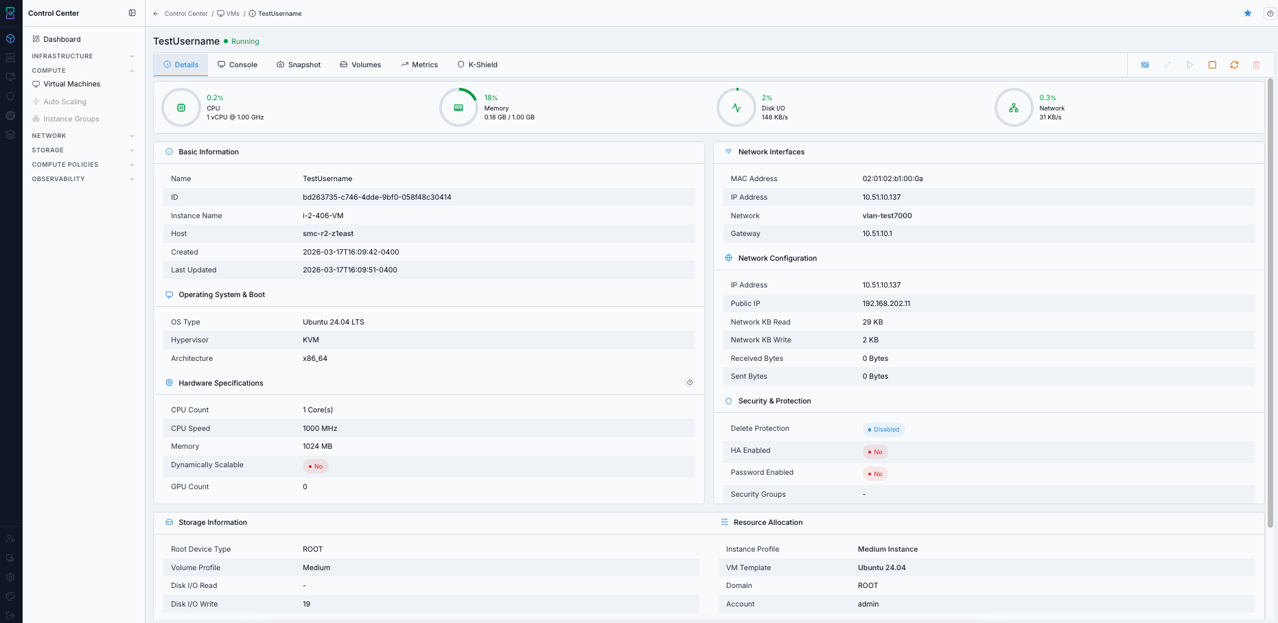
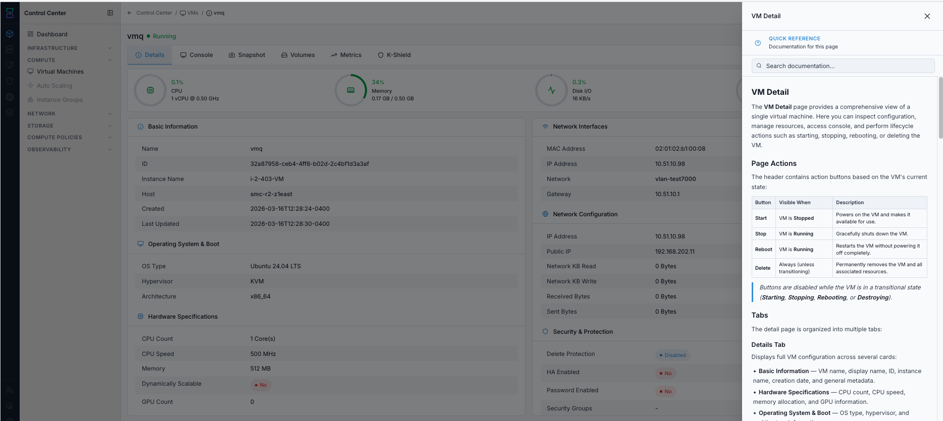
Details tab - configuration and identity.
What this screenshot shows:
VM header with state and tab navigation
Basic Information,Operating System & Boot, andHardware SpecificationscardsNetwork interface and security/protection settings in the right panel
Steps:
Open VM details.
Stay on
Detailstab.Compare identity, hardware, network, and storage values against expected configuration.
Expected Outcome:
VM identity, hardware, network, and ownership values are visible for comparison against the expected configuration.
If this fails:
Refresh the detail page and reopen the
Detailstab to rule out a stale UI session.Confirm the VM is still reachable from the management plane and not in a state transition.
Check Observability Events/Alerts for metadata-load or API errors tied to the VM before retrying.
7.1. Basic Information
Identity and metadata for the selected VM.
Field |
Description |
|---|---|
Name |
Display name of the VM. |
ID |
Unique system identifier (UUID) used in API calls and logs. |
Instance Name |
Internal hypervisor instance name (for example |
Host |
Physical host currently running this VM. |
7.2. Hardware Specifications
Compute resources allocated to this VM.
Field |
Description |
|---|---|
CPU Count |
Number of virtual CPU cores allocated. |
CPU Speed |
Clock speed cap per vCPU in MHz. |
Memory |
RAM allocated to the VM in MB. |
Dynamically Scalable |
Whether CPU/memory can be scaled without reboot (guest support dependent). |
GPU Count |
Number of GPU devices attached/passed through to the VM. |
Tip
Use the Scale Instance action in the header toolbar to adjust CPU and memory without recreating the VM.
7.3. Operating System and Boot
OS and hypervisor configuration for the VM.
Field |
Description |
|---|---|
OS Type |
Guest operating system display name. |
Hypervisor |
Virtualization technology running this VM. |
Architecture |
CPU instruction set architecture (for example |
7.4. Network Interfaces
One entry per virtual NIC attached to the VM.
Field |
Description |
|---|---|
MAC Address |
Unique hardware MAC address of the VM interface. |
IP Address |
Private IP assigned to this NIC in the guest network. |
Network |
Guest network this NIC is connected to. |
Gateway |
Default gateway for this NIC subnet. |
Note
VMs can have multiple NICs connected to different guest networks.
7.5. Network Configuration
VM-level network traffic and public connectivity details.
Field |
Description |
|---|---|
IP Address |
Primary private IP of the VM. |
Public IP |
Public/floating IP associated with the VM, if assigned. |
Network KB Read |
Total network data read since VM start. |
Network KB Write |
Total network data written since VM start. |
Received Bytes |
Raw bytes received by the VM. |
Sent Bytes |
Raw bytes sent by the VM. |
7.6. Security and Protection
VM protection and availability settings.
Field |
Description |
|---|---|
Delete Protection |
Prevents accidental VM deletion when enabled. |
HA Enabled |
Starts the VM on another host if the current host fails. |
Password Enabled |
Indicates whether guest password reset is supported via platform controls. |
Security Groups |
Number of applied firewall/security-group rules. |
Tip
Enable Delete Protection on production VMs and use HA Enabled for critical workloads.
7.7. Storage Information
Disk configuration and cumulative I/O details for this VM.
Field |
Description |
|---|---|
Root Device Type |
Storage backend type for the root disk (for example |
Volume Profile |
Volume profile applied to attached data disks, if any. |
Disk I/O Read |
Total disk read operations since VM start. |
Disk I/O Write |
Total disk write operations since VM start. |
Disk KB Read |
Total data read from disk since VM start. |
Disk KB Write |
Total data written to disk since VM start. |
7.8. Resource Allocation
Cloud assignment context for tenancy and placement.
Field |
Description |
|---|---|
Instance Profile |
Compute profile controlling CPU and memory limits. |
VM Template |
Base image used to create this VM. |
Domain |
Domain this VM belongs to for multi-tenancy. |
Account |
Account owner of this VM. |
Zone |
Availability zone where this VM is deployed. |
Host |
Physical hypervisor host currently running this VM. |
Expected Outcome:
Configuration and runtime metadata are validated before operations.
8. Console Tab - Direct CLI Access
When to Use:
Use Console when SSH/RDP is unavailable, when using boot-image install flow, or for emergency guest access.
Purpose:
Access the guest directly from the browser to complete install and validate boot behavior.
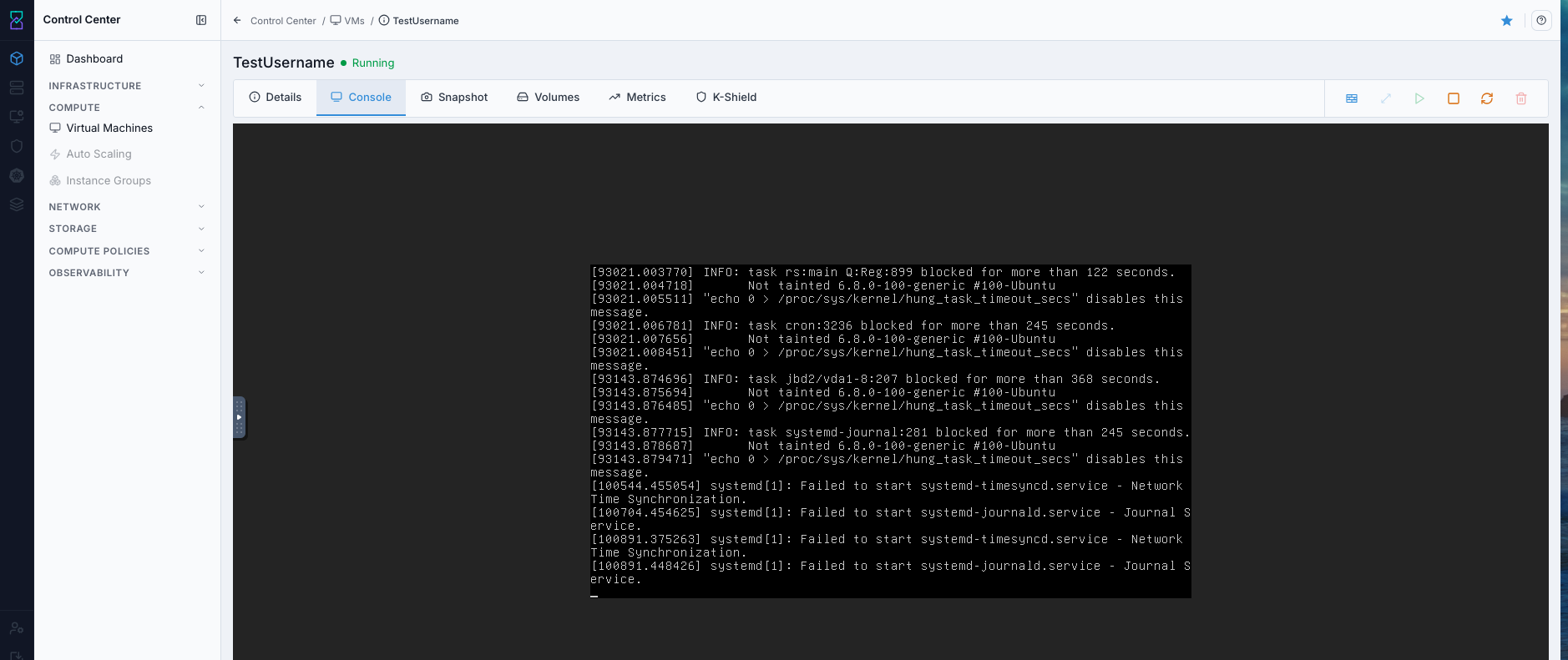
Browser-based VM console.
What this screenshot shows:
Console tab open while VM is
RunningLive guest output visible in the embedded console view
Console components:
VNC Consolefor browser-based guest accessConsole session list/details when active console connections exist
Steps:
Open VM details.
Ensure VM is in
Runningstate (start it if needed).Click Console tab.
Confirm login prompt appears.
Sign in with guest OS credentials.
Use Console for:
First boot verification
Boot image installer flow
Emergency troubleshooting
Why this matters:
Gives direct access when network services (SSH/RDP) are not ready
Required for boot-image-based OS installation flow
Helps diagnose boot and login issues quickly from one place
Expected Outcome:
Interactive VM terminal session is available in browser.
Warning
If console is blank, check platform console proxy/system VM health.
Console Troubleshooting
Symptom |
Likely Cause |
First Check |
|---|---|---|
Blank console page |
Console proxy/session service issue |
Verify console proxy/system VM health |
Keyboard input not accepted |
Browser session focus/capture issue |
Reopen console in a fresh session |
Login prompt never appears |
Guest not fully booted |
Check VM state and recent lifecycle actions |
If this fails:
Confirm the VM is
Runningand that console proxy or required system VM services are healthy.Reopen the console in a fresh browser session and allow any blocked pop-up or session prompts.
Check Observability Events/Alerts for console or system-VM errors before retrying.
9. Snapshot Tab - Backup and Recovery
When to Use:
Create snapshots before high-risk guest changes and restore snapshots when rollback is required.
Purpose:
Provide a rollback option for VM state and data.
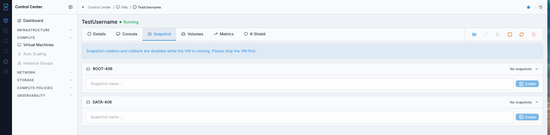
Snapshot creation workflow.
What this screenshot shows:
Snapshot tab showing per-volume snapshot controls
Snapshot name input and
Createaction for each attached volumeRunning-state warning banner indicating snapshot creation/rollback requires VM stop first
9.1. Why Snapshots
rollback safety before changes
recovery from failed updates
change validation and testing
Why Snapshot is important:
Reduces risk before patching, upgrades, or configuration changes
Provides a fast rollback point if the VM becomes unstable
Supports safer experimentation in test and staging workflows
Snapshot vs Backup (important):
Snapshot: platform rollback on the storage path.
Backup: independent copy for recovery from host/storage/site failure.
Do not treat snapshots as full backup strategy for production workloads.
9.2. Create Snapshot
When to Use:
Use this before high-risk guest changes so you have a rollback point for the selected VM volume.
Purpose:
Create a point-in-time restore marker you can use if patching, upgrades, or config changes fail.
Steps:
Stop VM.
Open Snapshot tab.
Select volume.
Enter snapshot name.
Click
Create.Confirm latest snapshot entry.
Snapshot success indicators:
Snapshot name appears in list for selected volume
Snapshot entry updates
Restore point is available for rollback workflow
Expected Outcome:
New snapshot is listed for selected volume.
Warning
Snapshot creation can be blocked while VM is running.
If this fails:
Confirm the VM is in the required power state for snapshot creation and refresh the
Snapshottab before retrying.Verify the selected volume is still attached, supports snapshots, and has enough backend capacity for the new restore point.
Check Observability Events/Alerts for the VM name, target volume, and action timestamp, then retry after correction.
9.3. Restore Snapshot
When to Use:
Use this when you must roll back a VM volume to a known-good snapshot state.
Purpose:
Restore VM volume data/state to the selected snapshot to recover from failed changes.
Steps:
Open
Snapshottab.Locate target snapshot by name.
Select restore action for that snapshot.
Confirm restore prompt and impact.
Confirm restore completes and VM state stabilizes.
Expected Outcome:
VM state/data returns to selected snapshot point.
Warning
Restoring a snapshot can overwrite newer guest changes. Validate rollback intent before confirming.
If this fails:
Confirm the target snapshot still exists for the correct VM volume and that the VM is in the required state for restore.
Validate the rollback target carefully and ensure no newer guest changes are still expected to be preserved.
Check Observability Events/Alerts for the VM name, snapshot name, and restore timestamp, then retry after correction.
10. Volumes Tab - Storage Management
When to Use:
Use this tab when reviewing VM disk layout or attaching/detaching data disks.
Purpose:
Control VM storage safely without changing VM identity or compute profile.
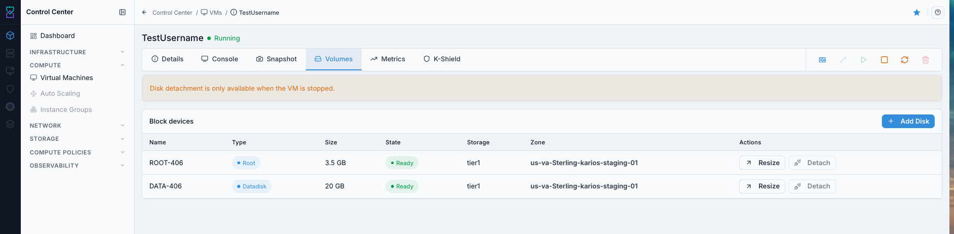
Volumes tab showing ROOT and DATADISK volumes.
Volume types:
ROOT: OS disk, always attached
DATADISK: additional storage, attach/detach by policy
Why Volumes are important:
Separates OS disk from application/data disks for better management
Enables controlled storage expansion without rebuilding the VM
Improves recovery planning by isolating critical data volumes
Common actions:
Add volume (
+)View volume details
Detach DATADISK (if allowed)
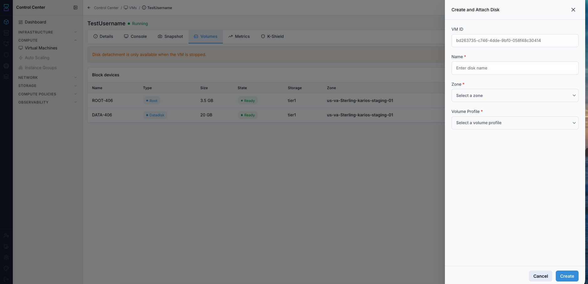
Create and Attach Disk drawer opened from the Volumes tab.
Steps:
Attach: add DATADISK for application/data growth.Detach: remove DATADISK only after guest-side unmount and data validation.View Details: confirm size, type, and state before changes.
Expected Outcome:
Volume inventory and attach/detach state are visible and manageable per policy.
Warning
Do not detach ROOT volume. For DATADISK, always unmount inside guest OS first.
If this fails:
Confirm you selected the correct volume and that guest-side unmount or application shutdown is complete before detach.
Verify the volume state, storage pool health, and current VM state allow the requested disk action.
Check Observability Events/Alerts for attach/detach or storage-side failures before retrying.
11. Metrics Tab - Performance Monitoring
When to Use:
Use this tab when a VM feels slow, resource limits are suspected, or you need trend validation after changes.
Purpose:
Correlate VM performance signals to workload behavior and right-sizing decisions.
Monitor:
CPU
memory
disk I/O
throughput
network behavior
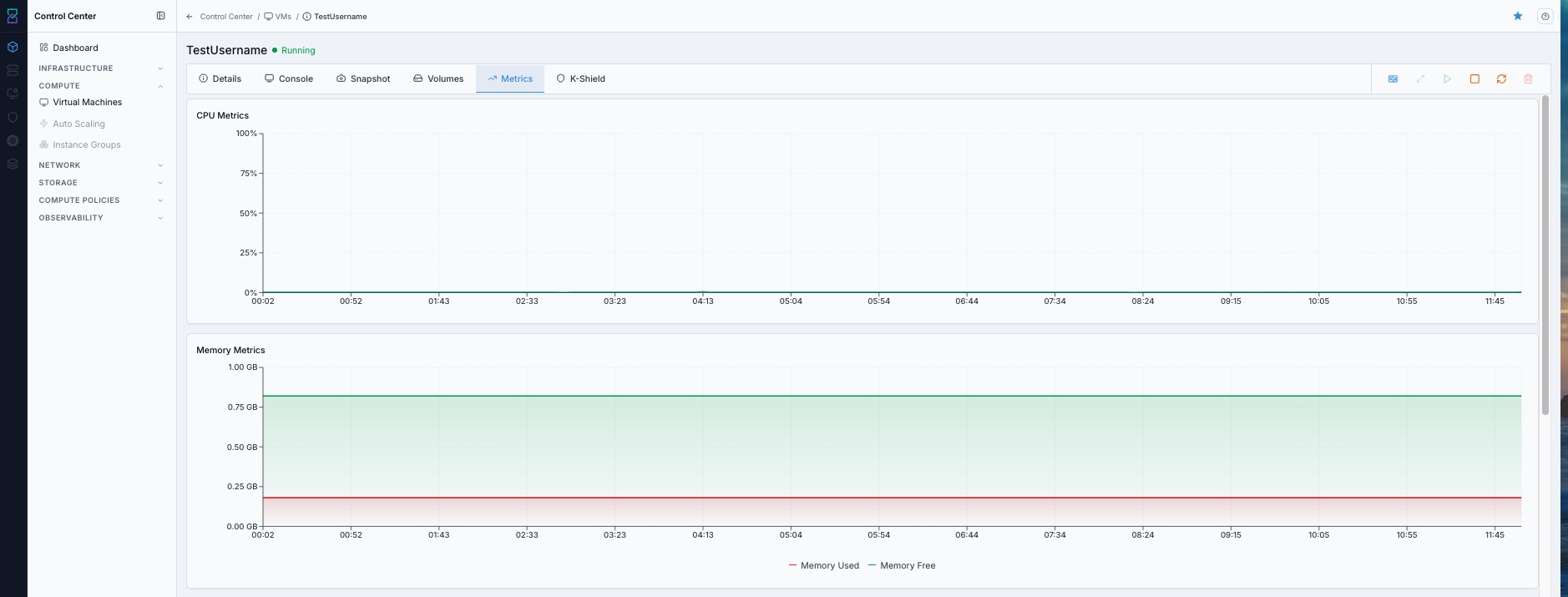
Metrics tab with CPU and memory trend charts.
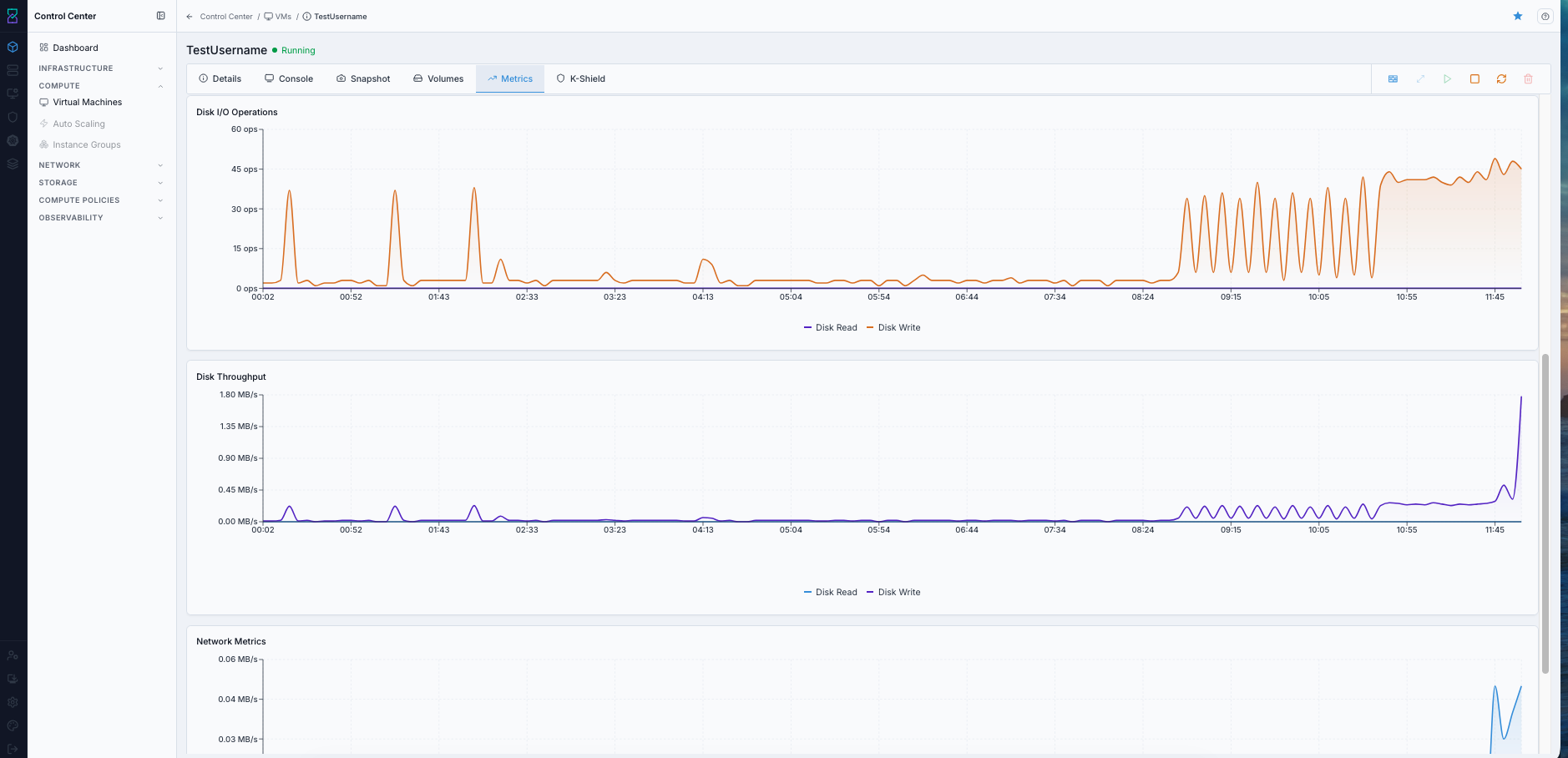
Metrics tab with disk I/O operations, throughput, and network trend charts.
Tip
Use metrics timeline to correlate spikes with deployments or incidents.
Metric interpretation quick guide:
Signal |
Typical Pattern |
Action |
|---|---|---|
CPU sustained high |
High utilization over long window |
Check workload saturation and resize/optimize if needed |
Memory near limit |
Frequent near-max memory usage |
Review memory pressure and right-size VM |
Disk I/O spikes |
Sharp read/write bursts |
Correlate with backup/jobs and storage tier capability |
Network throughput anomalies |
Unexpected in/out changes |
Validate workload behavior and network path health |
Expected Outcome:
Resource trends are visible for CPU, memory, disk, and network.
12. Karios Shield Tab - Security Scanning
When to Use:
Use this tab after VM provisioning and after remediation cycles to validate security posture.
Purpose:
Run VM-level scans, track findings history, and export evidence for audits.
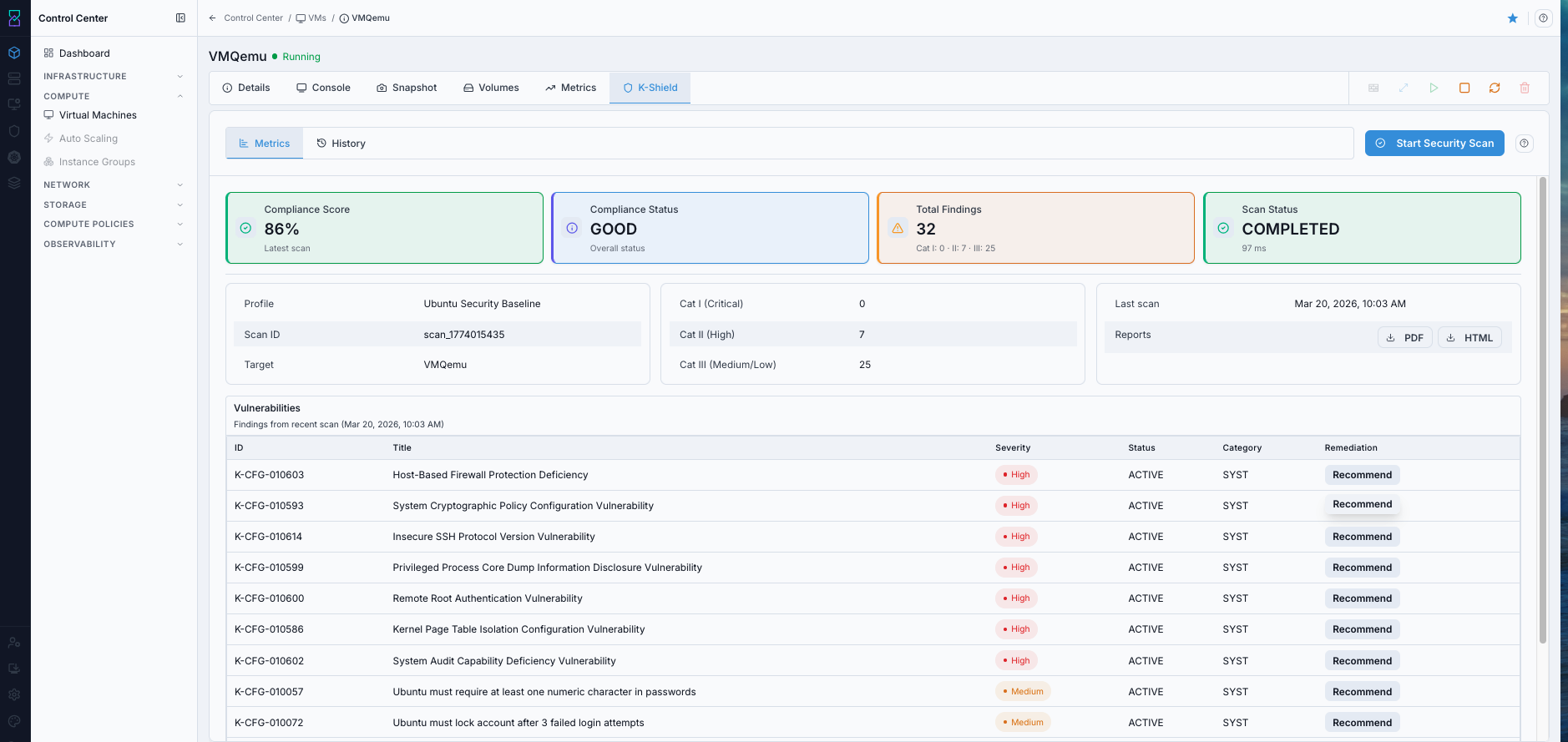
Karios Shield metrics with compliance and findings.
What this screenshot shows:
Metricssub-tab with compliance score, compliance status, total findings, and scan statusProfile, scan ID, severity breakdown, report export buttons, and findings table
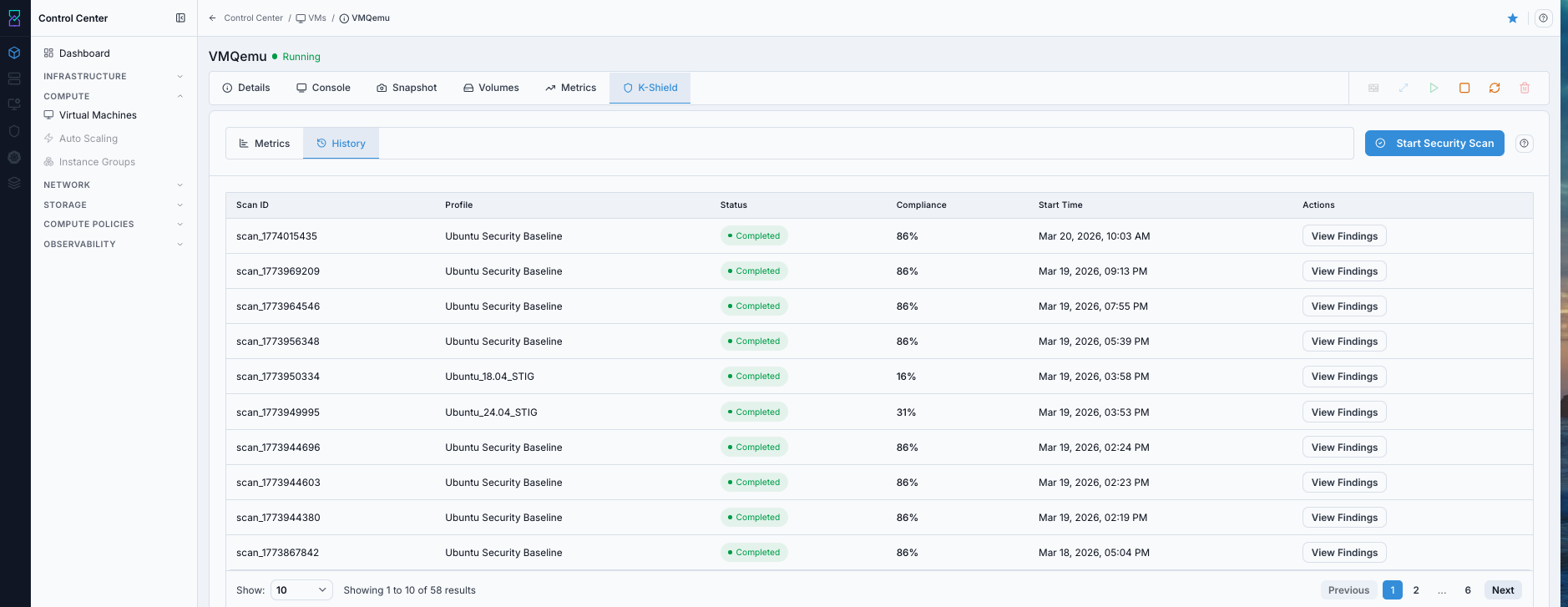
Karios Shield scan history.
What this screenshot shows:
Historysub-tab with scan rows andView FindingsactionCompliance fields used for trend tracking
12.1. Karios Shield Screen Components (What You See)
Top actions and tabs:
Start Security Scanbutton (top-right): starts a new security scan for this VMMetricstab: current/latest scan summary and vulnerability listHistorytab: previous scans with status/compliance and detail actions
Metrics summary cards:
Compliance Score (percentage)
Compliance Status (for example: GOOD)
Total Findings (with severity split)
Scan Status (for example: COMPLETED)
Metrics detail panels:
Profile, Scan ID, Target
Severity counts: Cat I, Cat II, Cat III
Reports buttons:
PDFandHTMLVulnerabilities table with columns like ID, Title, Severity, Status, Category, Remediation
History table:
Scan ID
Profile
Status
Compliance
Actions (
View Findings)
12.2. Run Security Scan (Step-by-Step)
Open VM details.
Open
Karios Shieldtab.Click
Start Security Scan.Confirm status updates to
COMPLETED.Stay on
Metricsto review results.
Expected Outcome:
New scan result appears in Metrics and is added to History.
12.2.1. Enabling VM Scanning by OS Type
Use this before running scans from the VM Karios Shield tab.
Ubuntu Instances
To enable automated security scanning on an Ubuntu VM, provision the VM with Ubuntu VM Scan in VM User Data.
Important
Scanning works only when Ubuntu VM Scan user data is selected during VM provisioning.
If this option is not selected, the VM is created normally, but VM scanning capabilities are not enabled.
When to Use:
Use this when provisioning an Ubuntu VM that must support Karios Shield scanning.
Purpose:
Enable scan communication automatically by deploying Ubuntu with the required Ubuntu VM Scan user data.
Steps:
Navigate to VM provisioning.
Select Ubuntu as the operating system.
In the
VM User Datadropdown, selectUbuntu VM Scan.Complete remaining provisioning steps and deploy the VM.
Run scan using
Ubuntu_Baselineprofile, or upload and use your own custom profile.
What Ubuntu VM Scan user data does:
Installs the
QEMU Guest Agent.Enables and starts the agent service during boot.
Allows the scanning system to communicate with the VM through the hypervisor.
Expected Outcome:
Ubuntu VM is provisioned with
Ubuntu VM Scanuser data and is ready for Karios Shield scan execution.
If this fails:
Confirm
Ubuntu VM Scanwas selected during provisioning and that the VM was deployed from the intended template or boot image.Log in to the guest and verify
qemu-guest-agentis installed, enabled, and running.Check Observability Events/Alerts for guest-agent or scan-communication errors before retrying.
Windows Instances
To enable automated security scanning on a Windows VM, install QEMU Guest Agent manually inside the VM.
Unlike Ubuntu VMs, Windows VMs do not automatically install the guest agent during provisioning.
Important
Scanning works only after QEMU Guest Agent is installed and running inside the Windows VM.
If the guest agent is not installed, scans fail because the scanning system cannot communicate with the VM.
Steps to enable scanning on a Windows VM:
Provision the Windows VM normally.
Log in to the VM using RDP or VM console.
Install
QEMU Guest Agentinside the VM.Confirm
QEMU Guest Agentservice is running.Run scan using
Windows_Baselineprofile, or upload and use your own custom profile.
Verifying installation:
Open
Servicesin Windows.Locate
QEMU Guest Agent.Confirm service status is
Running.
What QEMU Guest Agent enables:
Communication between the scanning system and VM through the hypervisor.
Safe execution of scanning operations.
Collection of required system information for scan output.
Note
Guest agent installation is required only once per VM. After installation, scanning continues to work after VM restart.
12.3. Actions in Metrics Tab
Use these actions directly from Karios Shield:
Click
Start Security Scanand choose a validated profile.Click
PDForHTMLin Metrics to export reports.Click
Recommendin vulnerability rows to view remediation guidance.
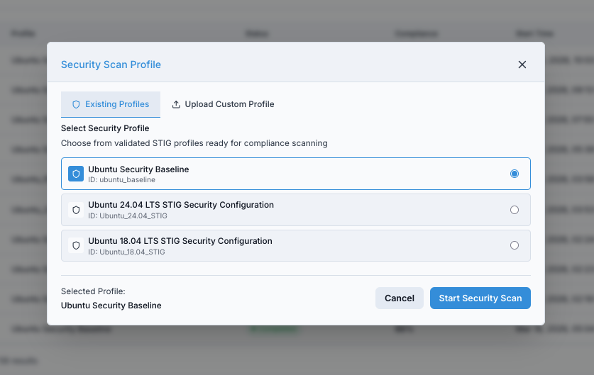
Security scan profile selection dialog.
What this screenshot shows:
Existing Profilesand custom profile upload optionsProfile list with selected baseline and
Start Security Scanconfirmation
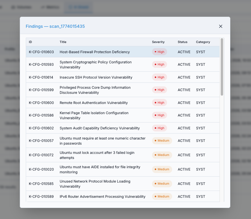
Scan findings modal.
What this screenshot shows:
Findings table for a selected scan ID
Vulnerability ID, title, and severity columns for remediation triage
What each action does:
Start Security Scan: initiates a new scan with selected profile.PDF/HTML: gives evidence/report artifact for sharing and audits.View Findings/Recommend: opens finding context for remediation.
Expected Outcome:
You can export reports and start remediation from finding-level guidance.
12.4. Actions in History Tab
Open
Historysub-tab.Locate the scan row by scan ID.
Click
View Findingsin the row.
What this action does:
Opens the findings context for that historical scan so you can compare security posture across scans.
Expected Outcome:
You can review older scan outputs and track compliance trend consistency.
12.5. New User Workflow for Karios Shield
Run first scan with
Start Security Scan.Review Compliance Score and Total Findings.
Sort focus by severity (Cat I -> Cat II -> Cat III).
Use
Recommendon high-severity findings first.Apply remediation changes inside the VM.
Re-run scan and compare new results in
HistoryusingView Findings.Download
PDFreport for records.
Expected Outcome:
Security posture is measurable, remediations are traceable, and improvements are verifiable across scans.
Warning
Prioritize high-severity findings first and confirm remediation with a follow-up scan.
13. Auto Scaling
Auto Scaling automatically adjusts the number of virtual machines in a group based on real-time performance metrics, helping workloads keep the right amount of compute capacity as demand changes.
When to Use:
Use Auto Scaling when a workload should add or remove VM capacity automatically
based on metric thresholds instead of manual Scale Instance actions.
Purpose:
Maintain a bounded group of VMs behind a load balancer rule, with scale-up and scale-down policies controlling when VM members are added or removed.
13.1. Auto Scaling Dashboard
Path: Control Center -> Compute -> Auto Scaling
The Auto Scaling dashboard lists configured VM scaling groups with their current state and member counts. From here you can create new groups, enable or disable existing groups, and open group details.
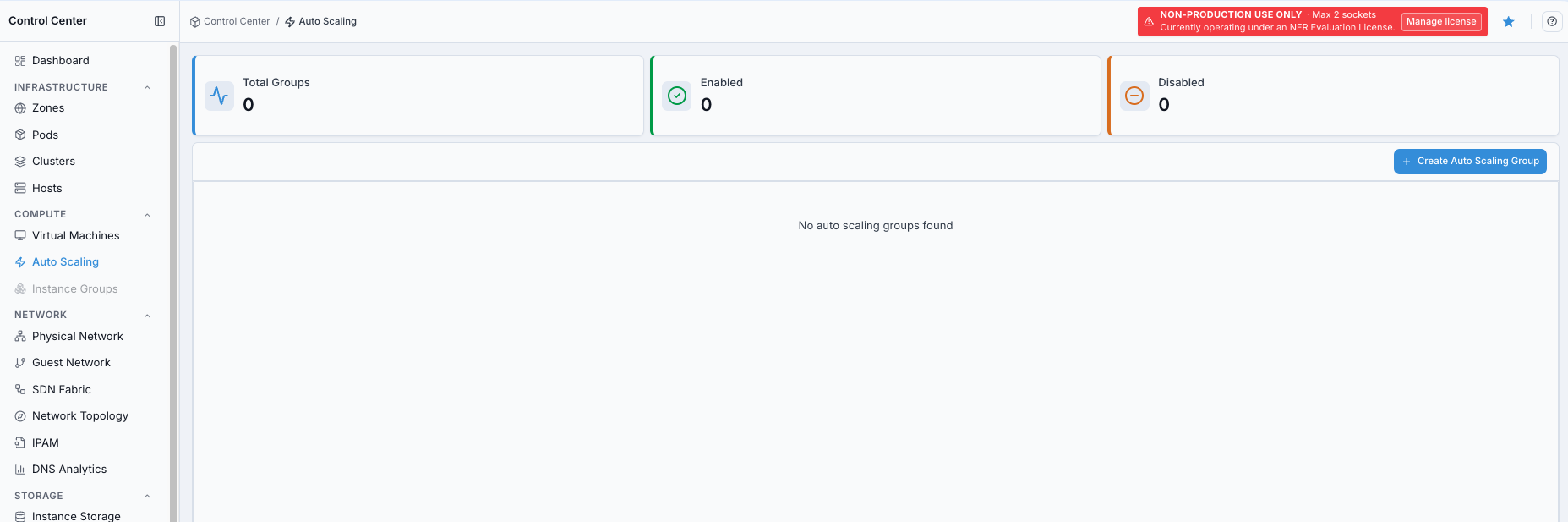
Auto Scaling dashboard.
What this screenshot shows:
Total Groups,Enabled, andDisabledsummary cardsEmpty-state message when no auto scaling groups exist
Create Auto Scaling GroupactionAuto Scalingselected in the Compute navigation
Summary cards at the top provide a quick snapshot:
Card |
Meaning |
|---|---|
Total Groups |
Number of auto scaling groups configured in the environment. |
Enabled |
Groups that are actively monitoring metrics and scaling VMs. |
Disabled |
Groups that exist but are paused and will not trigger scaling actions. |
13.2. Auto Scaling Group Table
The main table lists each group and its current operating limits.
Column |
Description |
|---|---|
Name |
Unique identifier for the auto scaling group. Click a row to open the detail page for that group. |
State |
|
Load Balancer Rule |
Load balancer rule associated with the group. Traffic is distributed across VMs managed by this group. |
Min / Max Members |
Lower and upper bounds for how many VMs the group can maintain. |
Interval |
How frequently, in seconds, the auto scaling engine checks metric counters against policy thresholds. |
Available VMs |
Current number of VMs actively running under this group. |
13.3. Creating an Auto Scaling Group
Click Create Auto Scaling Group to open the three-step creation wizard.
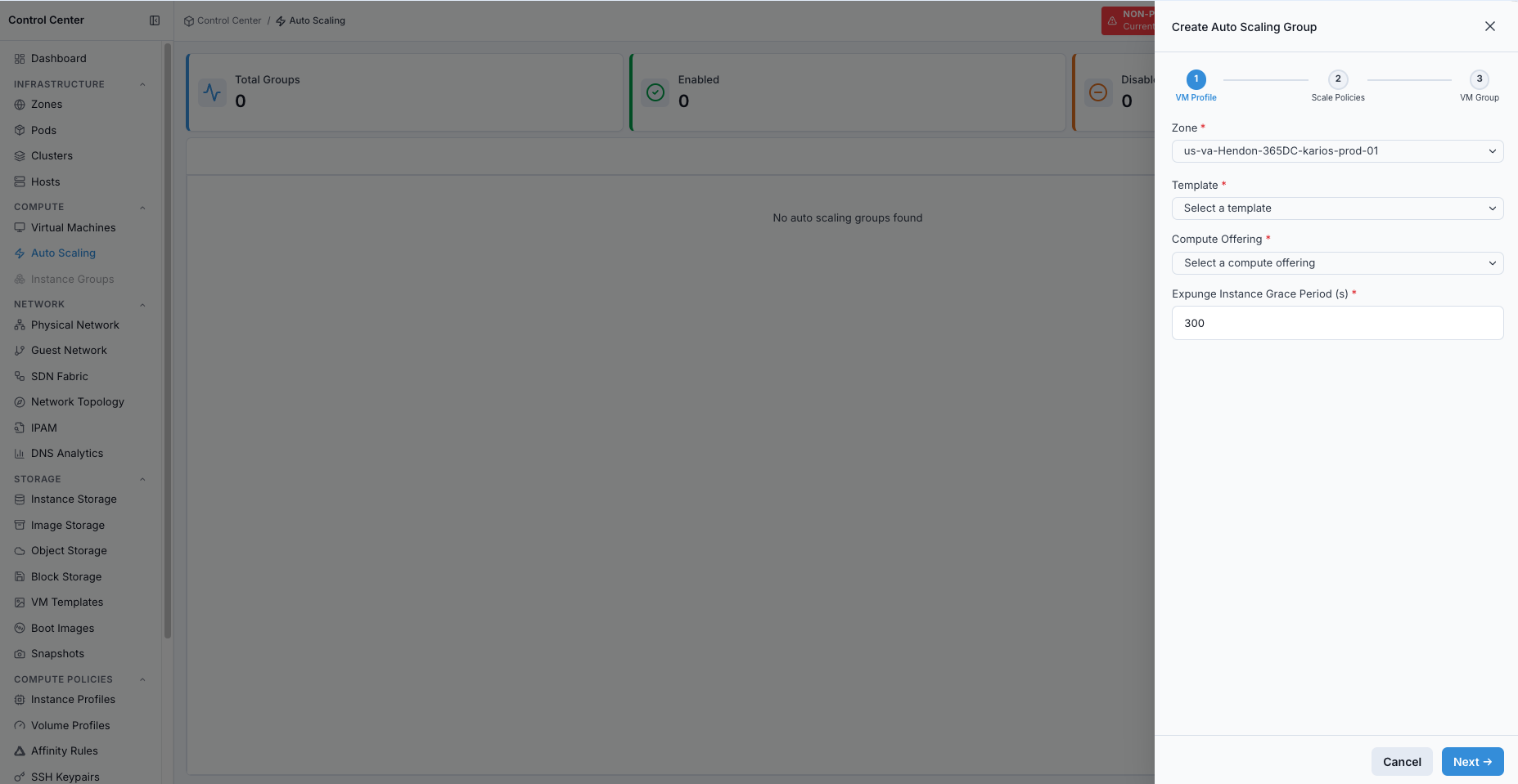
Create Auto Scaling Group wizard.
What this screenshot shows:
Three-step wizard:
VM Profile,Scale Policies, andVM GroupRequired
Zone,Template,Compute Offering, andExpunge Instance Grace Period (s)fieldsNextaction to continue to scale policy configuration
Step 1 - VM Profile
Define what each scaled VM looks like:
Zone
Template
Compute offering
Expunge instance grace period before removing a scaled-down VM
Optional networking, storage, and key pair parameters
Step 2 - Scale Policies
Configure two policies:
Scale Updefines the metric counter, threshold, and timing that triggers adding a new VM.Scale Downdefines the conditions that remove a VM from the group.
Each policy references:
Counter, such as CPU or memory
Relational operator, such as
GTorLTThreshold value
Duration, in seconds, that the condition must hold
Quiet time, or cooldown period, between consecutive scaling actions
You can select an existing counter or create a new counter inline.
Step 3 - VM Group
Set the group name, link the group to a load balancer rule, and configure minimum members, maximum members, and polling interval.
13.4. Enabling and Disabling Groups
Use the toggle action on any row to enable or disable a group without deleting it. Disabling a group stops scaling evaluations while preserving the group configuration and existing VMs.
13.5. Deleting a Group
Deleting a group removes the scaling configuration. Existing VMs managed by the group are not automatically destroyed, but they are no longer managed by Auto Scaling.
13.6. Related Topics
The Auto Scaling page also includes an in-app help panel for quick reference while configuring groups.
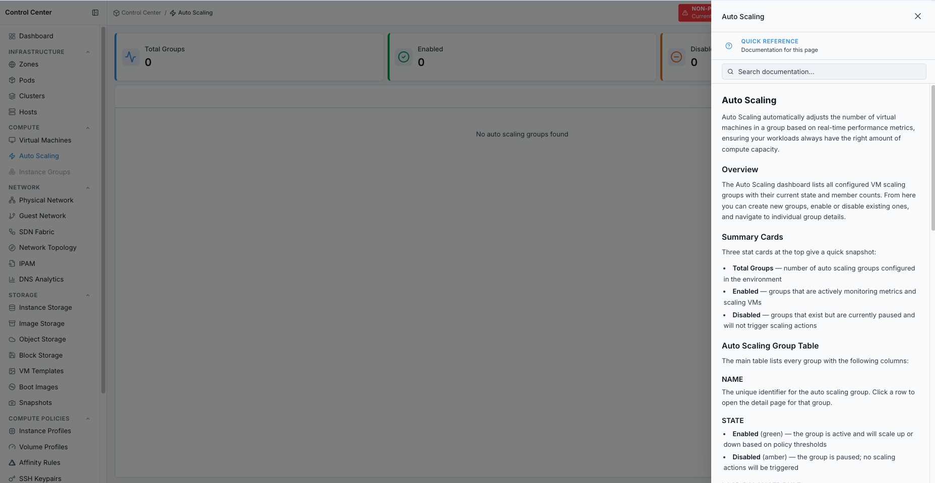
Auto Scaling help panel.
Auto Scaling Detail: VM profile, policies, and group configuration for a specific group.
Virtual Machines: manage individual virtual machines.
Instance Profiles: define CPU and memory allocations for scaled VMs.
14. Troubleshooting and Quick Reference
14.1. Common Issues and Fixes
Symptom |
Likely Cause |
Immediate Action |
|---|---|---|
Empty Create VM dropdowns |
Missing prerequisite objects |
Validate profile/media/storage readiness |
VM stuck |
Host/storage/media readiness issue |
Check host/storage availability and active alerts |
VM in |
Provisioning/runtime failure |
Review action error text and correlated alerts |
Console blank |
Console proxy/session issue |
Verify console/system VM services |
Snapshot action unavailable |
Policy/state limitation |
Confirm VM state and snapshot support |
No VM templates/boot images selectable |
Images not registered/ready |
Register media and confirm |
Karios Shield no output |
Guest-side compatibility/profile issue |
Validate agent/profile compatibility and scan status |
Metrics empty |
VM stopped or telemetry delay |
Ensure VM is running and recheck after telemetry refresh |
14.3. First VM Checklist (New User)
Host ready in Forge
Zone enabled
Instance profile exists
Volume profile exists
Network available
Instance Storage up and Image Storage reachable
VM template or boot image in ready state
14.4. Quick VM Creation Flow
VM Template path:
Compute -> Virtual Machines -> Create VM -> Name -> Zone -> Instance Profile -> VM Template -> Volume Profile -> Network -> Provision VM
Boot Image path:
Compute -> Virtual Machines -> Create VM -> Name -> Zone -> Instance Profile -> Boot Image -> Volume Profile -> Network -> Provision VM -> Console install
14.5. Key Reminders
0 VMsinitially is normalVM Template path uses preconfigured OS images
Boot Image path requires manual OS installation via Console
Take snapshots before high-risk changes
Check state filters when VM is not visible
Use Metrics and active alerts together for troubleshooting
14.6. Escalation Data to Capture
If issue persists, collect the following before escalation:
VM name and ID
Current VM state and last known good state
Exact failing action and related alert details
Relevant error text, VM state, and active alert details
Host/zone/account context
Whether issue reproduces after retry/re-login
Screenshot of affected UI state
14.7. Provisioning Failure Recovery
If VM provisioning fails mid-process:
Do not repeatedly re-run the same failed request without checking VM state and active alerts.
Capture the exact error text shown in action dialogs/notifications.
Correlate with alert timestamps in
Observability -> Alerts.Validate dependency objects:
instance profile exists and has capacity
target network is operational
VM template/boot image is
ReadyInstance Storage pool is
Up
Recovery decision:
Capacity issue: pick smaller instance profile or add host resources.
Network/media issue: fix dependency, then provision new VM.
Unknown recurring failure: escalate with alert evidence + VM ID + related alert details.
Expected Outcome:
New users can recover from common issues and complete VM operations end-to-end.
→ Next: Nodes
Expected Outcome
After this section, you should be able to:
Create and manage VMs end-to-end
Create and manage Auto Scaling groups for VM capacity changes
Use detail tabs (Console, Snapshot, Volumes, Metrics, Karios Shield)
Troubleshoot common VM lifecycle issues
What To Do Next
Provision one test VM using a VM template and confirm it reaches
Running.Validate console access and baseline network connectivity from that VM.
Continue to Storage to manage volumes and capacity safely.