Guest Networks
3.1. What are Guest Networks?
Guest networks are where VMs attach and receive their runtime IP connectivity.
Quick selection:
Isolated: private network with built-in network services.Shared: flat subnet model with explicit VLAN/IP inputs.L2: pure Layer-2 segment with no built-in services, carried as either a VLAN or a VXLAN segment depending on the offering you pick; you provide DHCP/gateway externally.
What These Terms Mean:
CIDR: Classless Inter-Domain Routing notation for subnet size (for example10.1.0.0/16).NIC: Network Interface Card attached to a VM.NAT: Network Address Translation for private-to-public traffic mapping.Gateway: default route endpoint used by VMs to reach other networks.
For create/delete tasks, use Sections 3.5 and 3.6.
3.2. Network States
Which states a guest network moves through is decided by the network offering, not by the network type:
Offerings that take an explicit VLAN or VNI and are not persistent are created directly in
Setupand stay there - that is their normal steady state, not an incomplete one. This covers Shared networks,Karios-VLAN-Isolated,Karios-VXLAN-Isolated, everyKarios-L2*offering, and every VPC tier offering.Offerings that allocate the VNI for you (Auto-VNI), or that are persistent - for example
Karios-VXLAN-Auto-Isolatedand the*-AutoScaleofferings - progressAllocated -> Implementing -> Implemented.
Important
Do not use Implemented as the readiness signal. Most Karios offerings never reach it,
even though the virtual router is up and a Source NAT IP is present. Judge readiness from
the network’s virtual router being ``Running`` (Guest Network -> Virtual Routers)
and from the network being offered during VM provisioning.
State/action quick reference:
State |
What It Means |
Typical Operator Action |
|---|---|---|
Allocated |
Created, services not initialized yet. Seen on Auto-VNI and persistent offerings before first activation |
Attach/provision first VM to activate services |
Implementing |
Network services are being initialized |
Wait and monitor; avoid concurrent config changes |
Implemented |
Operational with services initialized. Only Auto-VNI and persistent offerings reach this state |
Attach additional VMs and continue normal operations |
Setup |
The segment is registered and the network is usable. Steady state for every offering that takes an explicit VLAN/VNI and is not persistent (Shared, |
Normal - attach VMs. If VMs have no connectivity, check the virtual router, not the state |
3.3. First VM Activation and Guest-Network State Change
After creating an isolated guest network, first-VM provisioning performs initial network-service activation.
Expected state flow:
On an Auto-VNI or persistent isolated offering (for example
Karios-VXLAN-Auto-IsolatedorKarios-VXLAN-Isolated-AutoScale), first-VM provisioning triggers the progressionAllocated -> Implementing -> Implemented.On an isolated offering that takes an explicit VLAN or VNI (for example
Karios-VLAN-IsolatedorKarios-VXLAN-Isolated), the network is already inSetupand stays there. Services still come up - watch the virtual router rather than the network state.Additional VMs on the same guest network use the existing initialized network services.
Tip
Watch the network’s virtual router reach Running while the first VM is created. On the
offerings that do progress, you can also watch the state move from Allocated to
Implemented.
If the network remains Implementing after provisioning tasks complete, review the If this fails guidance in the related Guest Network tasks in this section. A network sitting in Setup is not stuck - see 3.2. Network States.
3.4. Viewing Guest Networks
Access: Control Center → Network → Guest Network
This dashboard shows all guest networks in the selected environment and provides the main entry points for create, review, and delete actions.
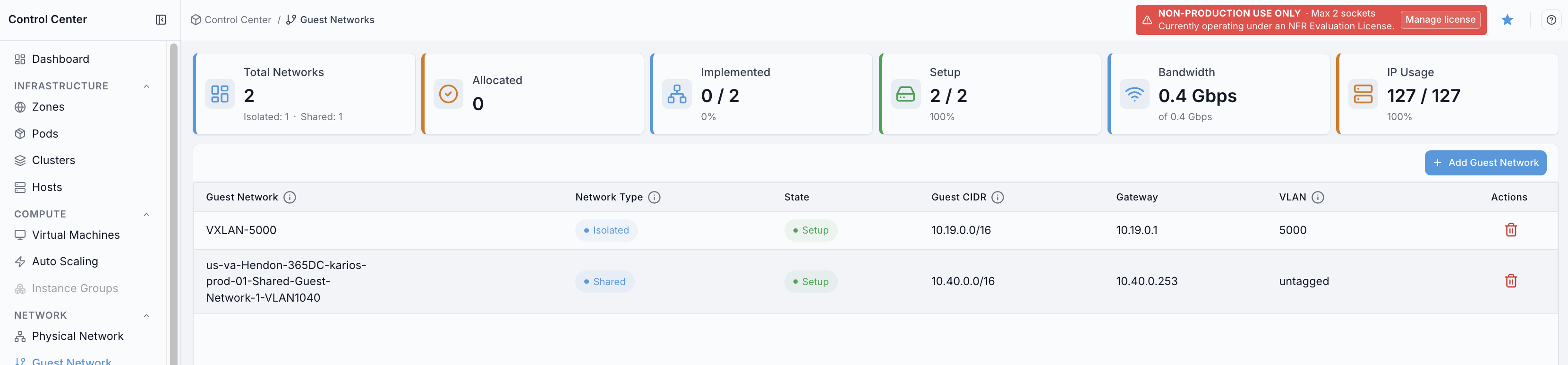
Actions you can perform:
Click
+ Add Guest Networkto open the guest-network creation form.Click a value in
Guest Networkcolumn to open that network’s details page.Click the trash icon in
Actionsto delete a guest network row.Review
Statebadges to confirm whether a network is ready for VM attachment.Hover the
iicons in table headers (where shown) for inline field help.
The page also provides:
Guest Networks / Virtual Routers sub-tabs (with counts) - switch to
Virtual Routersto review the routers backing guest networks.A scope dropdown to filter between
All,StandardandVPCnetworks (Allis the default).A keyword search to find a network by name, VNI, or archetype.
VXLAN visibility in this screen:
VXLAN-backed guest networks appear in the same
Guest Networktable as other network types.In the screenshot above,
VXLAN-5000is an example of a VXLAN guest-network row.Use the same actions for VXLAN rows: open details from
Guest Networkname, verifyState, and use rowActions.
Dashboard cards and definitions:
Card |
Definition |
|---|---|
|
Total count of guest networks in this view, with isolated and shared totals shown below the count. |
|
Count of networks currently in |
|
Implemented/active-state summary shown as count and percentage. |
|
Networks currently ready for workload attachment, shown as count and percentage. |
|
Aggregate bandwidth usage shown as used versus total capacity. |
|
Aggregate IP consumption shown as used versus total IPs. |
Table columns and definitions:
Column |
Definition |
|---|---|
|
Guest network name. Click to open details. The coloured dot beside the name indicates the network model - hover it to read |
|
Current network lifecycle state (for example |
|
IPv4 subnet assigned to the guest network. |
|
Default gateway for that guest subnet. |
|
Segment transport for the network: |
|
Count of VMs bound to the network. A non-zero count blocks deletion; click through to the VM list. |
|
Row-level action icons (for example delete). |
Use this screen first to validate guest-network readiness before VM deployment.
3.4.1. Open Guest Network Help Panel
When to Use:
Use this after reviewing the Guest Network dashboard when you need help text for fields and actions.
Purpose:
Open the dashboard help panel as a separate step so users can read quick-reference guidance before performing create/delete operations.
Steps:
Open
Control Center -> Network -> Guest Network.Click the top-right help icon.
Review the
Quick Referencecontent and use search to find specific field guidance.
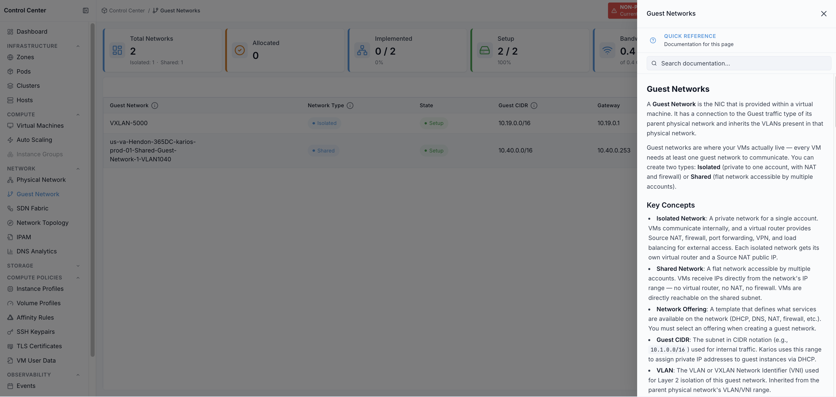
Expected Outcome:
Guest Networkshelp content opens in the right-side panel.You can review key concepts such as isolated networks, shared networks, network offerings, guest CIDR, and VLAN/VNI usage.
You can return to dashboard actions with clear field guidance.
If this fails:
Refresh the page and click the help icon again.
Confirm your account can access in-product help content.
Retry after reopening
Guest Network.
3.5. Creating Guest Network
Use this section when creating guest networks from Control Center -> Network -> Guest Network.
Step: Add Isolated Guest Network (from Guest Network page)
When to Use: Use this when creating a tenant-isolated network directly from the Guest Network module.
Purpose: Create an isolated guest network with the required offering and network parameters.
Steps:
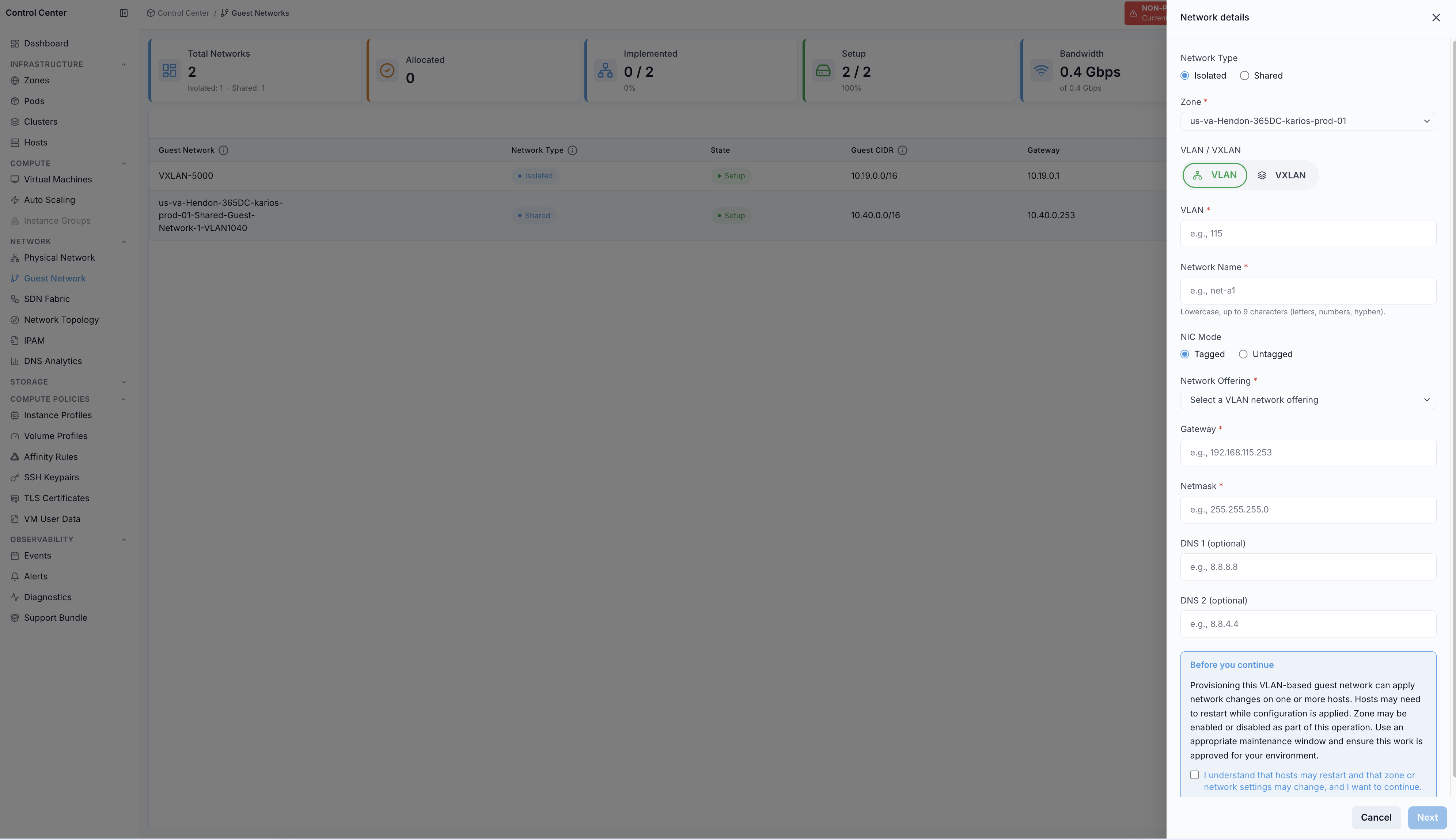
Open
Control Center -> Network -> Guest Network.Click
+ Add Guest Network.Keep
Network TypeasIsolated.Select
VLANorVXLANbased on the network segment you are creating.Complete the required network details.
Acknowledge the
Before you continuenotice when it appears (shown for VLAN-isolated networks).For a VLAN-isolated network, click
Nextand complete the NIC assignment step, then clickCreate Network. For a VXLAN-isolated network, clickCreate Networkdirectly.
Isolated-network fields:
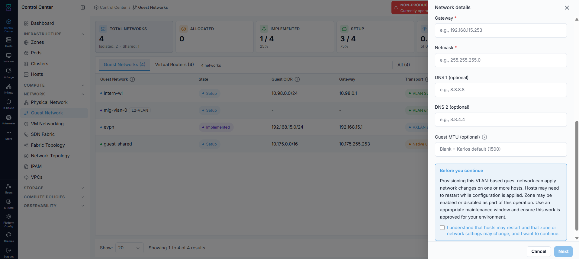
Zone(required)VLANorVXLAN (VNI)(required unless an Auto-VNI offering is selected - see below)Network Name(required)NIC Mode:TaggedorUntaggedwhen VLAN mode is selectedNetwork Offering(required; use a VLAN-capable or VXLAN-capable isolated offering)GatewayandNetmask(required)DNS 1andDNS 2(optional)Guest MTU(optional)
Note
If the selected network offering is an Auto-VNI offering, the VXLAN (VNI) field is
hidden and the platform allocates the VNI from the pool. Enter a VNI only for a manual
offering that requires one.
Note
For a VLAN-isolated network, scrolling down reveals the Before you continue notice:
provisioning a VLAN-based guest network can apply changes on one or more hosts, hosts may
need to restart, and the zone may be enabled or disabled during the operation. You must
check the acknowledgement box to proceed - plan this during a maintenance window.
VXLAN option (isolated):
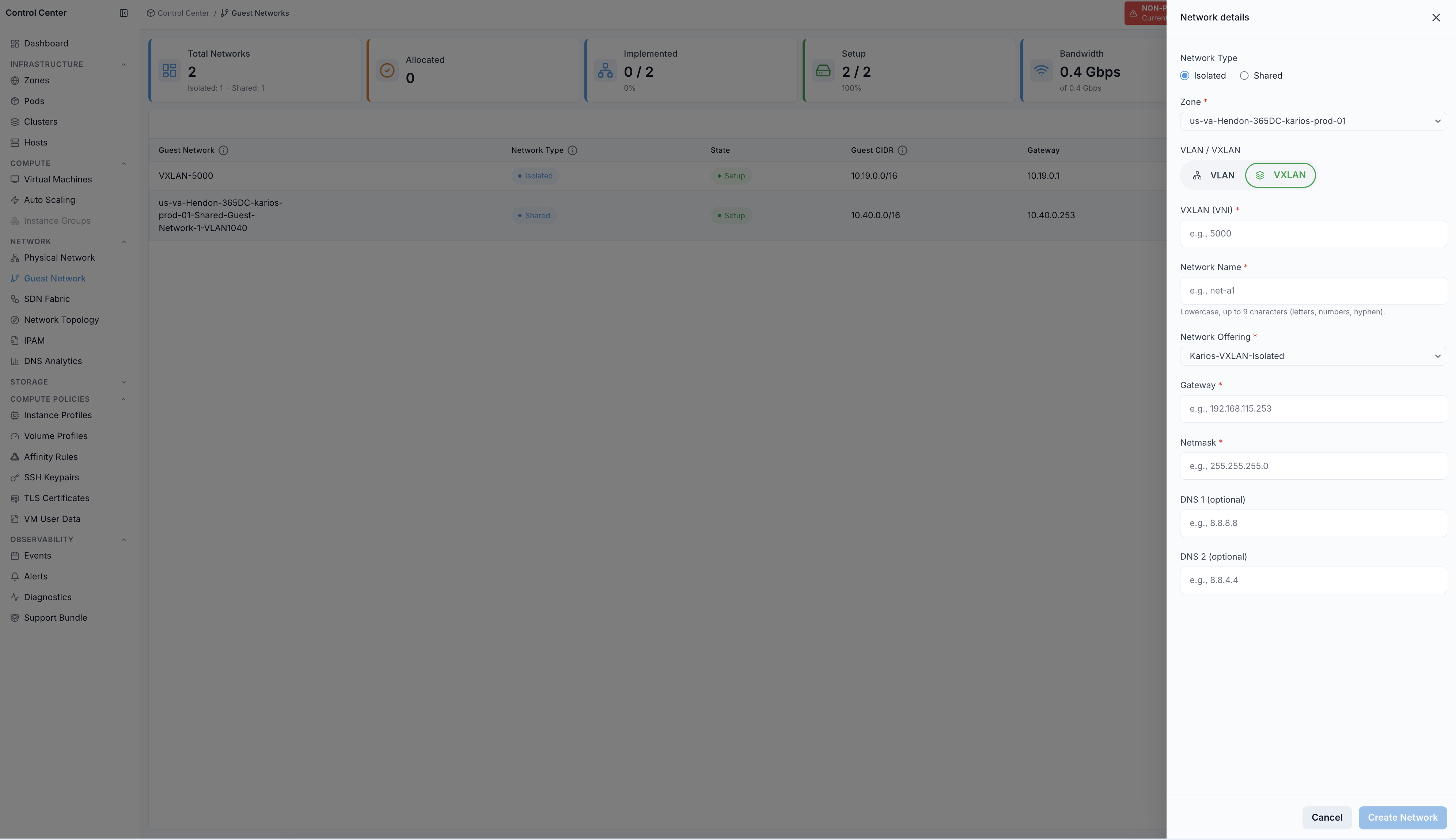
VXLAN-specific fields:
VXLAN (VNI)(required unless an Auto-VNI offering is selected)Network Offeringset to a VXLAN-capable isolated offeringGatewayandNetmask(required)DNS 1andDNS 2(optional)Guest MTU(optional)
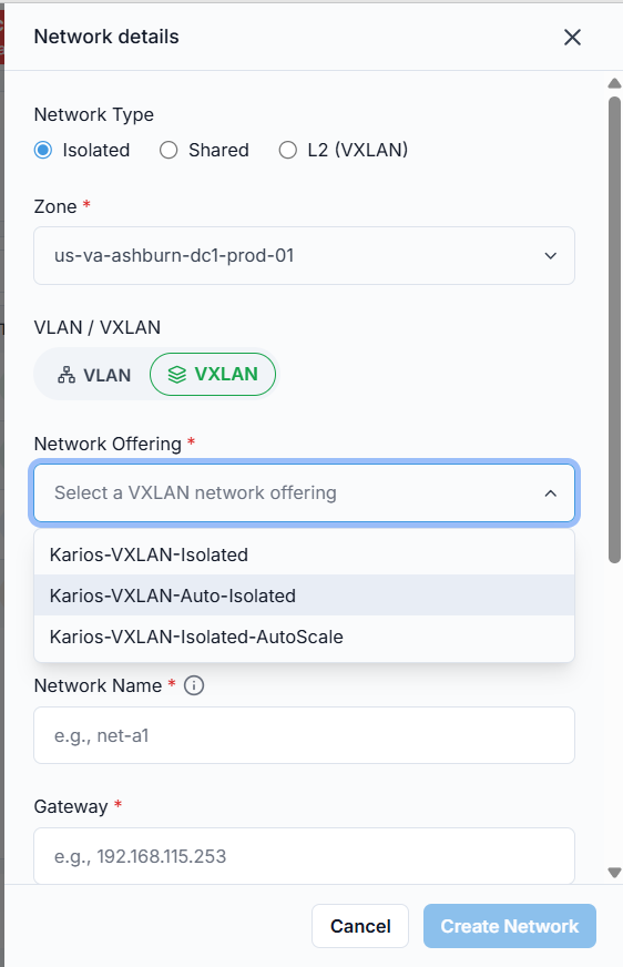
VXLAN-capable offerings vary by environment - for example Karios-VXLAN-Isolated
(manual VNI), Karios-VXLAN-Auto-Isolated (Auto-VNI, see the note above), and
Karios-VXLAN-Isolated-AutoScale (adds autoscaling). Pick the one matching the
capabilities this network needs.
Expected Outcome:
Karios provisions the network asynchronously. A progress panel tracks the work (bridge, network, virtual router) and reports completion, failure, or rollback - wait for it to finish before closing the wizard or retrying.
The new isolated network is then listed.
The state you see depends on the offering:
Setupfor an offering that takes an explicit VLAN/VNI,Allocated(thenImplemented) for an Auto-VNI or persistent offering. See 3.2. Network States.
Tip
Confirm the network appears in the list before attempting to create it again.
Warning
The network offering decides which services the network provides. It can be changed later, but only to a compatible offering, and the change restarts the network - choose deliberately.
If this fails:
Confirm required fields are not blank. A blank required field is rejected with a message naming the exact fields that are missing.
Confirm offering supports isolated mode.
Verify network name is unique in zone, and that the VLAN or VNI is not already recorded in IPAM - Karios checks both before creating.
UntaggedNIC mode is rejected when the physical network already carries an untagged guest network: untagged networks share one broadcast domain, so use a tagged VLAN, a VXLAN VNI, or a different base NIC instead.For a VXLAN network, creation is also blocked when the EVPN fabric is not registered, its rollout failed or is still running, BGP peering is not established, or the nodes have not converged. Fix the fabric first - see SDN Fabric, section 4.6 (
When the Fabric Blocks Creation).
Step: Add Shared Guest Network (from Guest Network page)
When to Use: Use this when creating a shared guest network directly from the Guest Network module.
Purpose: Create a shared guest network with explicit VLAN and IP-range settings.
Steps:
Open
Control Center -> Network -> Guest Network.Click
+ Add Guest Network.Select
Network Type -> Shared.Complete the required network details.
Click
Create Network.
Shared-network fields:
Zone(required)Network Offering(required; must support shared networks)PVLAN Type(optional; defaults tonot a PVLAN; a private VLAN can only be created by a ROOT admin, on an Advanced zone, on a Shared or L2 network, with IPv4)VLAN(required; oruntaggedwhere applicable)Network Name(required)NIC Mode:TaggedorUntaggedStart IPandEnd IP(required)GatewayandNetmask(required)DNS 1andDNS 2(optional)Guest MTU(optional)
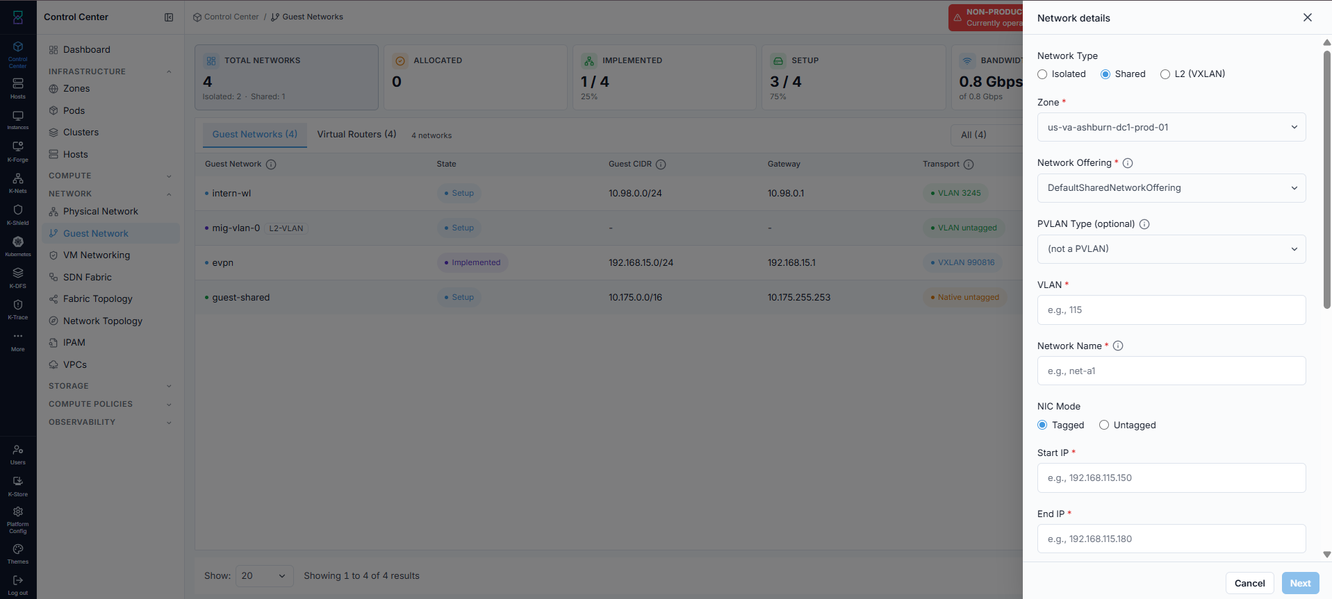
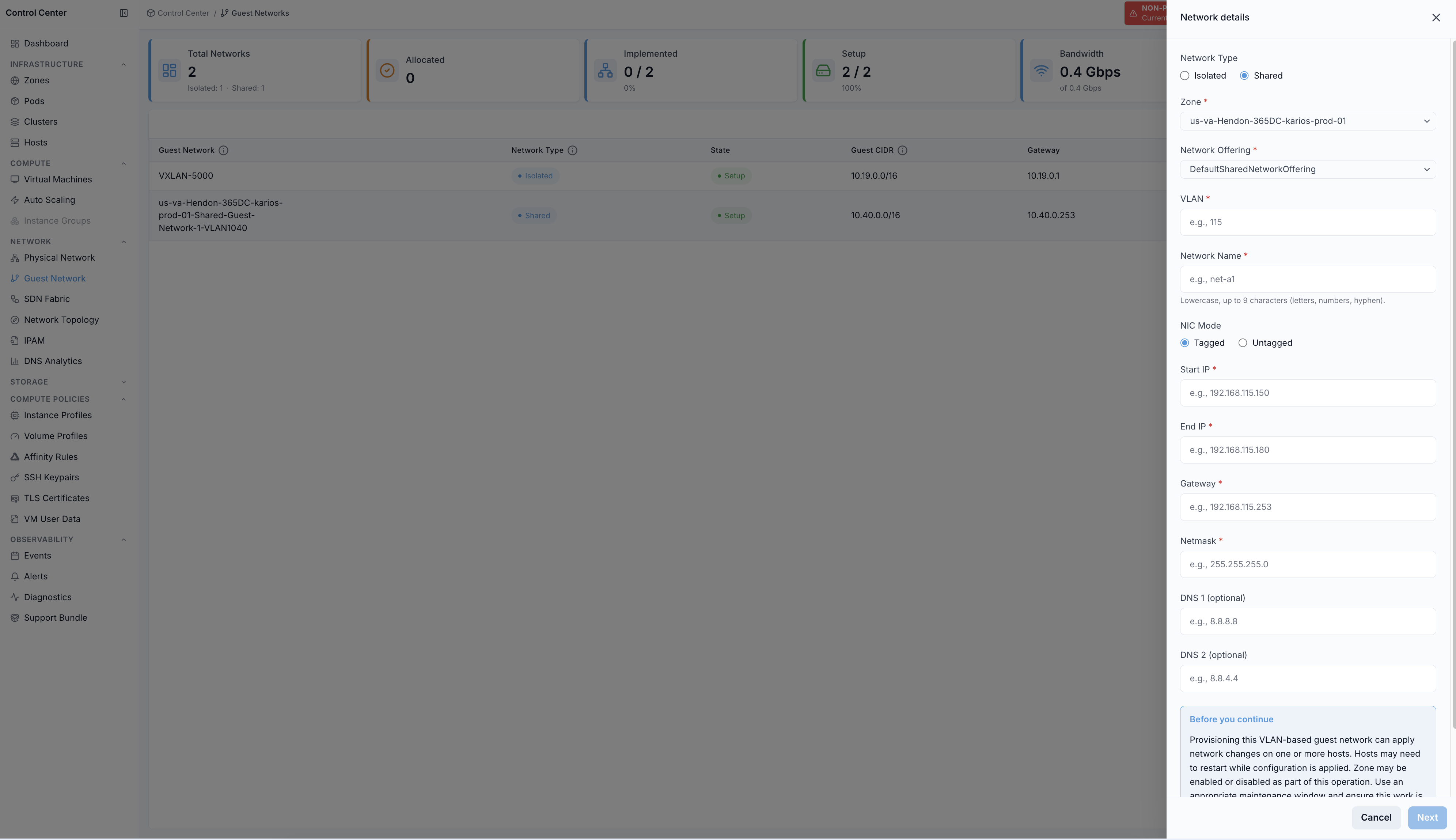
Scrolling down reveals the same Before you continue notice shown for VLAN-isolated
networks (see the note under Step: Add Isolated Guest Network (from Guest Network page)
above) - acknowledge it to proceed.
Expected Outcome:
Shared network is listed in
Setupafter successful creation.VMs consume IPs from the provided range.
Expected Behavior
Shared networks do not require isolated-network service initialization.
Warning
Common First-Time Mistake
Wrong: gateway placed inside VM allocation pool.
Symptom: IP conflicts or unstable connectivity.
Correct pattern:
CIDR:
192.168.10.0/24Gateway:
192.168.10.1(reserved)Start IP:
192.168.10.10End IP:
192.168.10.250
Tip
If you do not know Physical Network ID, use Add Shared Guest Network from Physical Network.
That flow pre-populates the physical network context.
If this fails:
Verify subnet math and gateway reachability.
Verify no overlap with existing ranges.
Verify VLAN value is valid for target physical network.
Step: Add L2 Guest Network (from Guest Network page)
When to Use: Use this when the workload brings its own addressing (external DHCP/gateway) and only needs a Layer-2 segment - for example lift-and-shift VMs or network appliances.
Purpose: Create a pure Layer-2 guest network - carried either as a native VLAN or as a VXLAN segment on the EVPN fabric, depending on the offering you pick - with no virtual router and no Karios-provided DHCP, DNS, gateway, or NAT.
Steps:
Open
Control Center -> Network -> Guest Network.Click
+ Add Guest Network.Select
Network Type -> L2.Choose
VLANorVXLANin theVLAN / VXLANselector. This picks the transport and filters the offering list to that family.Complete the required network details.
Click
Create Network.
L2-network fields:
Zone(required)VLAN / VXLAN(required; selects the transport for the segment)Network Offering(required; defaults toKarios-L2in VXLAN mode andKarios-L2-VLANin VLAN mode)VLAN IDin VLAN mode, orVXLAN (VNI)in VXLAN mode (required - there is no Auto-VNI L2 offering)Network Name(required)VGT trunk passthrough - guest tags 802.1Q internally(optional; lets the workload tag its own VLANs inside the segment)Allowed inner VLANs (informational)(optional; shown when trunk passthrough is enabled)
Expected Outcome:
L2 network is listed with type
L2.VMs attached to it get a NIC on the segment but no IP from Karios - your external DHCP or static configuration assigns addressing.
Note
L2 networks have no gateway or netmask - those services are intentionally not provided,
and no virtual router is spawned. The form still renders DNS 1 / DNS 2 fields, but
they are not used for an L2 network. If you need built-in services, use an Isolated
network instead.
If this fails:
Verify the VLAN ID or VNI is unused and within the range configured for the physical network.
Verify network name is unique in zone.
A VXLAN/EVPN L2 offering (
Karios-L2,Karios-L2-MAC-Mobileand the rest of that family) is additionally gated on the fabric: creation is blocked when the EVPN fabric is not registered, its rollout failed or is still running, BGP peering is not established, or the nodes have not converged - see SDN Fabric, section 4.6 (When the Fabric Blocks Creation).The same VXLAN/EVPN offerings also require an operator acknowledgement of the top-of-rack switch configuration. The first attempt is refused with the message
Physical fabric ack required for L2 EVPN VXLAN segmentplus a set of vendor switch-config snippets; the network is not created until the matching configuration has been applied and acknowledged. TheAdd Guest Networkform surfaces this as an error - the acknowledgement dialog itself is presented in the migration network-mapping wizard.
Note
Neither the fabric gate nor the acknowledgement applies to the native-VLAN family
(Karios-L2-VLAN*) or to a trunk-passthrough segment: those ride the operator’s existing
VLAN physical network and need no EVPN fabric.
3.6. Guest Network Details
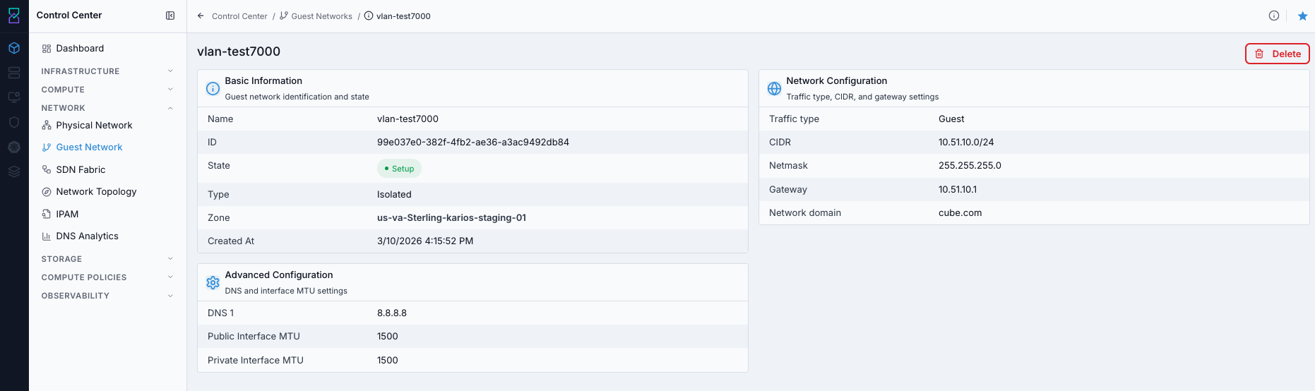
Step: Review Guest Network Details
When to Use: Use this when validating configuration and identity fields for one guest network.
Purpose: Inspect the selected guest network before VM attachment, change review, or troubleshooting.
Steps:
Open
Control Center -> Network -> Guest Network.Click a network name from the table.
Validate the
Basic Informationcard (Name,ID,State,Type,Network Offering,Zone,Created At,Tags) and theNetwork Configurationcard:IDfor API calls, automation, and log correlationStateandTypeCIDR,Netmask,GatewayDNSand MTU values in advanced fields
Expected Outcome:
You confirm the guest network identifier and whether core network values match design intent.
If this fails: 1. Refresh the guest network list and reopen the same row. 2. Confirm the network still exists and is visible in the table. 3. Confirm your account can access guest-network details.
Guest Network Service Tabs
For an Isolated network that is not a VPC tier, the detail page carries per-network
service tabs beside Details: Port Forwarding, Firewall, Load Balancing,
VPN, and Public IPs. Use them to manage that one network’s edge services without
leaving the network.
Shared and L2 networks, and networks opened as a VPC tier, show only Details:
An
L2network has no virtual router, so it has no edge services at all.A VPC tier’s rules belong to the VPC - manage them from VPCs (Network ACLs, Static NAT, VPN connections).
The same rules, across every network at once, are also listed under VM Networking.
Step: Delete Guest Network
When to Use: Use this when a guest network is no longer needed and has no required dependents.
Purpose: Remove a guest network from inventory and confirm it is no longer available for VM attachment.
Use the Guest network details screenshot shown in Task: Review Guest Network Details above.
Steps:
Open
Control Center -> Network -> Guest Network.Click the target network name.
In the details page, click the trash icon in the top-right action cluster.
Confirm deletion.
Return to guest network list and verify the row is removed.
Expected Outcome:
The guest network is removed from inventory.
It no longer appears as an attachable network during VM provisioning.
Warning
Delete only after detaching workloads and dependent services.
If this fails:
Check whether VMs or services are still attached.
Check whether related NAT/LB/firewall objects still reference this network.
Retry after dependencies are removed.
→ Next: VM Networking