Physical Networks
2.1. What are Physical Networks?
Physical Networks are zone-level templates for host bridge configuration. They model how cloud traffic flows under the hood and define the parent isolation policy used by guest networks.
Note
Karios provisions the zone’s physical network and all four traffic types (Management, Public, Guest, Storage) automatically during installation, and creates additional physical networks on demand when you add guest networks and register fabric switches (see 2.3). Multiple physical networks per zone are normal. Day-to-day operation does not require creating one by hand - review the existing rows first.
2.1.1. Key Concepts
Zone: every physical network belongs to exactly one zone.
Isolation Method: VLAN (Layer-2 tagging), or VXLAN (overlay tunneling) for tenant separation.
VLAN/VNI Range: pool consumed when new guest networks are created. VNI means
VXLAN Network Identifier.Traffic Types: Guest, Management, Public, and Storage traffic categories.
Broadcast Domain Range: scope of broadcast domains (
ZONEorPOD).Guest Network Inheritance: guest NIC networks inherit parent physical-network isolation settings.
2.1.2. Table Columns
Column |
Description |
|---|---|
Physical Network |
Network name. Click to open details. |
State |
|
Isolation Method |
Tenant isolation mode (VLAN or VXLAN). |
Underlay bridge |
Linux bridge on each KVM node that egresses this physical network’s traffic (for example |
Tags |
Labels used for organization and filtering. |
2.2. Physical Network Dashboard
When to Use:
Use this before creating, editing, or troubleshooting physical-network configuration.
Purpose:
Validate existing physical networks, isolation methods, and action availability from a single dashboard.
Path:
K-Nets -> Physical Network
Note
Every K-Nets -> path on this page is also reachable at
Control Center -> Network -> .... Non-root tenant accounts do not see the K-Nets
module and must use the Control Center path.
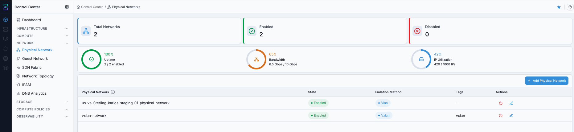
Dashboard usage:
Review each row for
StateandIsolation Methodbefore making changes.Click a
Physical Networkname to open details.Review the
Underlay bridgecolumn to confirm which host bridge carries each network.Use the info icon beside
Physical Networkin the table header for quick context.
Note
The physical-network list is read-only. There is no + Add Physical Network button
and no per-row edit or enable/disable action in the current UI - Karios provisions the
physical network and its traffic types automatically at install (see 2.3).
Expected Outcome:
You can identify the correct network row for your next action.
You can confirm whether target networks are
Enabledbefore creating dependent resources.
If this fails:
See Common screen checks before retrying this screen.
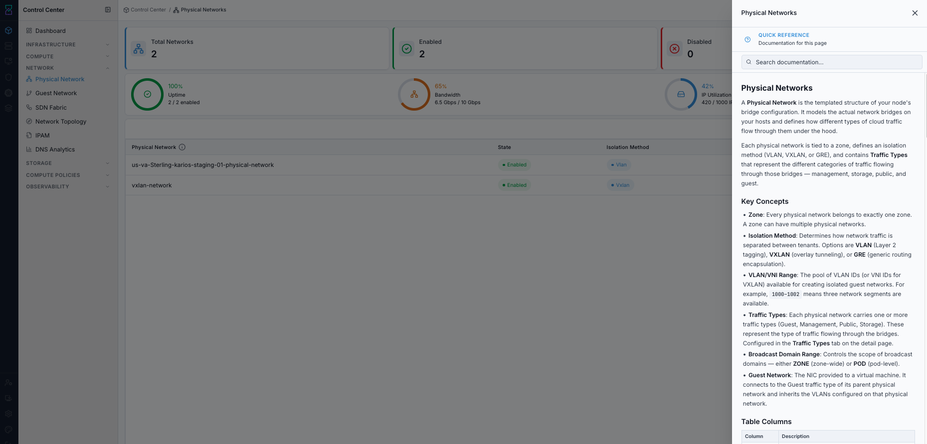
2.2.1. Open Physical Network Help Panel
When to Use:
Use this when you need inline definitions and quick-reference guidance for the Physical Network page.
Purpose:
Open the page help panel after reviewing the dashboard so field meanings and actions are clear.
Steps:
Open
K-Nets -> Physical Network.Click the top-right help icon.
Review the quick-reference panel and search inside it if needed.
Expected Outcome:
Physical Network page guidance opens in the side help panel.
You can continue dashboard actions with field-level context.
If this fails:
Refresh the page and click the help icon again.
Confirm your account can access in-product help content.
Retry after reopening
Physical Network.
2.3. Create Physical Network
Physical networks are created automatically - you rarely create one by hand:
At install, the installer provisions the zone’s Advanced physical network and its traffic types (Management, Public, Guest, Storage).
When you create a guest network, Karios provisions the backing physical network on demand: a per-bridge, VLAN-isolated physical network (named
nic-<bridge>, for examplenic-cloudbr0) for anIsolatedorL2guest network in VLAN mode, or a sharedvxlan-tagged physical network for a VXLAN guest network. During this the zone is briefly disabled and re-enabled, because the platform rejects physical-network creation on an enabled zone.A
Sharednetwork is the exception: it is attached by explicit physical-network ID, so an existing physical network whoseGuesttraffic type already egresses on the right bridge is reused as-is and nonic-<bridge>network is created.When you register a fabric switch (SDN Fabric), Karios creates the
karios-vxlan-fabricphysical network for the EVPN overlay. This runs in the background and is deliberately non-fatal: if the platform is briefly unavailable the save still succeeds, and the physical network is created on the next save or on the next restart of the network service.
Note
Multiple physical networks per zone are normal. A running zone typically shows the
installer-provisioned network plus one or more auto-created nic-<bridge> and
karios-vxlan-fabric networks. Review the existing rows on the dashboard before
assuming a network is missing.
As covered in 2.2, the Physical Network page has no create button; physical-network creation is automatic, or performed through the platform API for advanced automation. There is normally nothing to create here by hand.
Note
A physical network is not useful until at least one traffic type is configured. Karios configures the traffic types automatically for the networks it creates.
2.4. Physical Network Details
When to Use:
Use this to inspect one physical network before traffic-type configuration or edits.
Purpose:
Validate core network properties on the details page and move to
Traffic Typesfor traffic actions.
Steps:
Open
K-Nets -> Physical Network.Click the target physical network name in the table.
On the details page, review
Detailstab fields and openTraffic Typestab for traffic operations.
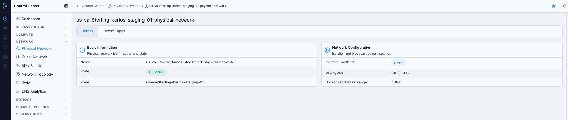
Details tab:
Basic Information:
Name,State,Zone,Tags.Network Configuration:
Isolation Method,VLAN/VNI,Broadcast Domain Range.
Note
A physical network’s own MTU is not configured on this page. The underlay MTU is
declared once at the installer/bootstrap layer. To see a bridge’s live MTU use
K-Nets -> Network Topology (node Bridges tab); the fabric-managed values are
shown on K-Nets -> SDN Fabric as Underlay MTU and VR uplink MTU, where
Underlay MTU is locked read-only once the live cluster value is known. The overlay
MTU is always derived as underlay MTU - 50; it is never entered separately. The
Guest MTU field on the guest-network create form is a different, per-network value.
Traffic Types tab:
Configure which traffic categories this physical network carries.
Available categories:
Guest,Management,Public,Storage.Traffic-type actions are performed from this
Traffic Typestab.Available actions vary by traffic type and your role permissions.
Expected Outcome:
The selected physical-network details page opens.
You can verify
Name,State,Zone,Isolation Method, andVLAN/VNIvalues.You can continue to
Traffic Typesfor traffic-type-specific actions.
If this fails:
Return to
Physical Networkdashboard and verify the correct row was selected.Refresh the page and retry opening the same network.
Verify your account has access to Network details pages.
2.5. Traffic Types
Traffic-type operations are documented in the specific sections below:
Guest Traffic
Purpose:
Manage the guest networks attached to a physical network.
Guest traffic represents whole VM networks carried by the parent physical network. Each guest network becomes a VM NIC network and consumes VLAN/VNI capacity from the parent physical-network range.
How Guest Networks Work:
A physical network defines a VLAN/VNI pool (for example
1000-1002).Creating a guest network consumes one VLAN/VNI from that pool.
VMs attached to that guest network receive NICs and IPs from the guest-network subnet.
Network type (
Isolated,Shared, orL2) determines routing model and access behavior.
Tip
Monitor VLAN/VNI usage in this table. If the range is exhausted, no new guest networks can be created until you expand the range or add a new physical network.
Guest Network Types:
Isolated:Private network model scoped to a tenant/account.
Uses virtual-router services from the selected offering (NAT, firewall, VPN, load balancing).
Source NAT egress is provided by isolated-network services.
Inbound access is controlled through NAT/firewall rules.
Shared:Flat subnet model that can be used across accounts.
No virtual-router NAT or firewall path for the guest network. A virtual router may still be deployed to provide DHCP, DNS, or user-data, depending on the selected offering.
VMs receive IPs directly from the configured shared-network range.
L2:Pure Layer-2 segment, carried either as a VXLAN VNI on the EVPN fabric or as a native 802.1Q VLAN on an existing VLAN physical network. You choose the encapsulation on the
VLAN / VXLANcontrol when you create the network.No virtual router, no gateway, no DHCP/DNS from Karios - your own network services handle addressing.
Use for lift-and-shift workloads that bring their own DHCP/gateway, or appliance-style VMs.
Note
Only the VXLAN-backed L2 family needs a configured EVPN fabric. The VLAN-backed L2 family rides the operator’s existing 802.1Q VLAN physical network and is exempt from the fabric readiness gate, so it still works when no fabric is configured.
Guest Networks Table Columns:
Column |
Description |
|---|---|
Name |
Guest network name. Click to open guest-network details. |
Type |
|
VLAN/VNI |
Assigned VLAN/VNI ID or |
Broadcast URI |
Broadcast-domain identifier (for example |
CIDR |
IPv4 subnet for the guest network. |
IPv6 CIDR |
IPv6 subnet when configured, otherwise |
Step: Open Guest Traffic Details Page
When to Use: Use this when you need to review guest networks on a specific physical network.
Purpose: Guest networks consume VLAN/VNI IDs from the parent physical network, so this is the primary place to verify capacity and network inventory.
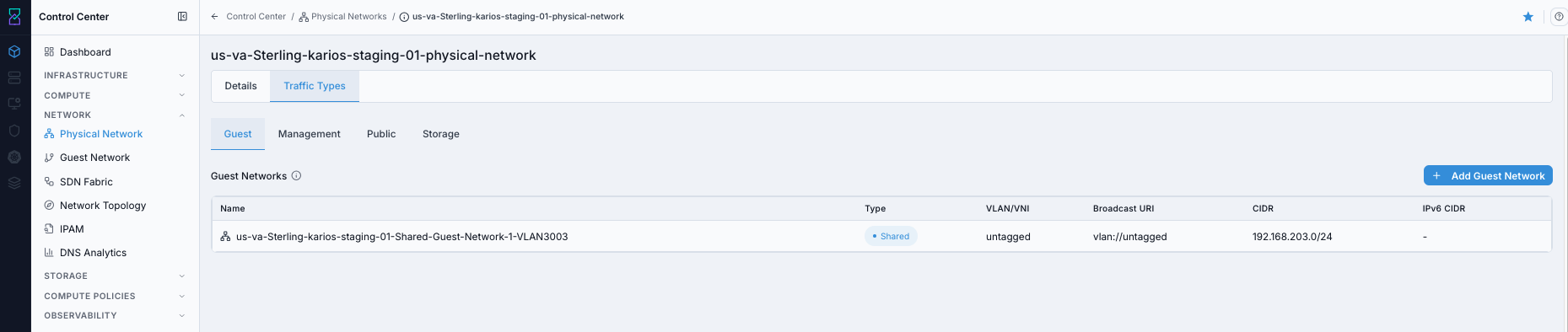
Details page shows:
A
Base Bridge · Guest Trafficpanel naming the Linux bridge (for examplecloudbr3) this traffic type egresses on each host.Guest network rows with
Name,Type,VLAN/VNI,Broadcast URI, andCIDRcolumns.+ Add Guest Networkaction for new network creation.
What you can do from this screen:
Open guest-network details by clicking a network name.
Launch guest-network creation for
Isolated,Shared, andL2workflows.Validate current VLAN/VNI consumption in this physical network.
Steps:
Open
K-Nets -> Physical Network.Click the target physical network name.
Click
Traffic Types.Click
Guest.
Expected Outcome:
You can review all guest networks on the selected physical network.
You can create guest networks and open each network’s detail page.
Continue with Page Help Review:
Click the top-right help icon.
Use the
iicon nearGuest Networksfor quick column definitions.For help-panel behavior, follow the same flow used in
2.2.1 Open Physical Network Help Panel.
If this fails:
1. Confirm you opened the intended physical network row.
2. Refresh and reopen Traffic Types -> Guest.
3. Verify your account can access networking pages.
Step: Add Isolated Guest Network (from Physical Network)
When to Use: Use this when you need a tenant-private network with isolated-network services.
Purpose: Isolated networks provide private VM networking with network services based on the selected offering.
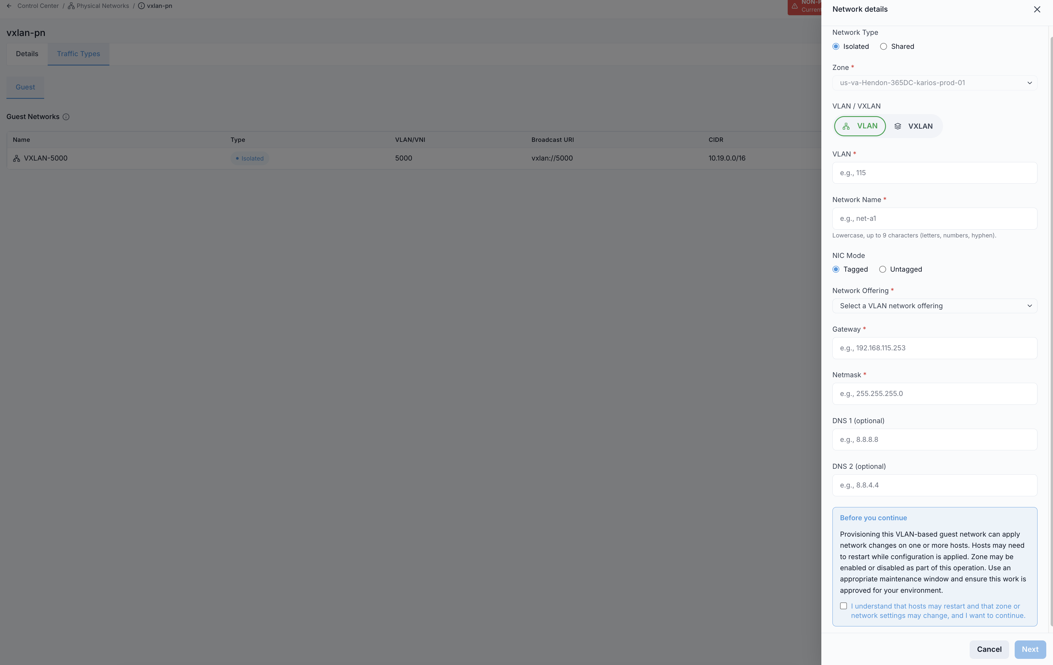
Step 1: choose Network Type as Isolated.
Steps:
From
Traffic Types -> Guest, click+ Add Guest Network.Keep
Network Typeset toIsolated.Choose
VLANorVXLANbased on the physical network design.Complete the required network details.
For a VLAN-isolated network, click
Nextand complete the NIC assignment step, then clickCreate Network. For a VXLAN-isolated network, clickCreate Networkdirectly.
Note
L2 networks - both VLAN- and VXLAN-backed - also create in a single step. There is
no NIC assignment step for them, and the primary button already reads
Create Network. Shared networks always take the NIC assignment step.
Isolated-network fields:
Zone(required)VLANorVXLAN (VNI)(required unless an Auto-VNI offering is selected - see below)Network Name(required)Network Offering(required; must support isolated-network capabilities)GatewayandNetmask(required)DNS 1andDNS 2(optional)Guest MTU(optional)NIC Mode:TaggedorUntaggedwhen VLAN mode is selected
Note
If the selected network offering is an Auto-VNI offering, the VXLAN (VNI) field is
hidden and the platform allocates the VNI from the pool. Enter a VNI only for a manual
offering that requires one.
Use the canonical field-level steps in Create Guest Network (Section 3.5).
VXLAN option in this flow:
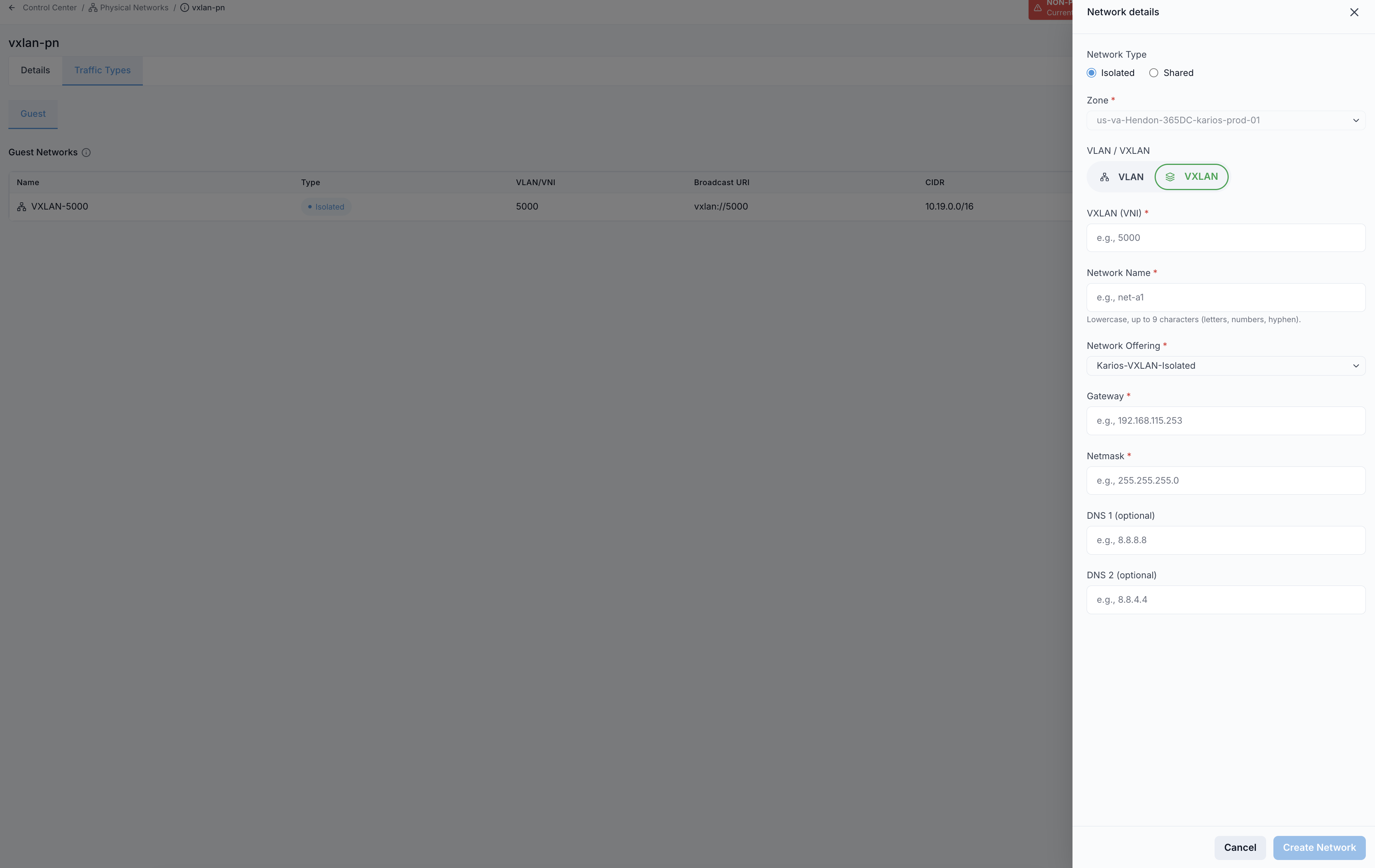
VXLAN-specific fields:
VXLAN (VNI)(required unless an Auto-VNI offering is selected)Network Offeringset to a VXLAN-capable isolated offeringGatewayandNetmask(required)DNS 1andDNS 2(optional)Guest MTU(optional)
Expected Outcome:
Creation is asynchronous: the request is accepted and a progress panel tracks bridge, network, and virtual-router provisioning live. The network does not appear in the list the instant you click
Create Network.Once provisioning finishes, the new network appears in guest network lists.
Which initial state you should expect depends on the offering:
Offering |
Initial state |
What happens next |
|---|---|---|
Takes an explicit |
|
|
Auto-VNI or persistent (for example |
|
Progresses |
Warning
Do not recreate a network because it sits in Setup and never reaches Implemented.
For an explicit-VLAN/VNI, non-persistent offering that progression does not exist, and
Setup is the healthy state.
If this fails:
Follow the Create Guest Network failure checks first (required fields, offering compatibility, name uniqueness).
For a VXLAN-isolated network, confirm the EVPN fabric is ready. Creation is blocked when the fabric switch is not registered, its rollout has not completed or has failed, nodes have not converged, or BGP peering to the fabric is not established. Register and verify the fabric first - see SDN Fabric. This gate does not apply to VLAN-isolated or VLAN-backed L2 networks.
Reopen
Traffic Types -> Guestdetails page and confirm whether the network row was created.
Step: Add Shared Guest Network (from Physical Network)
When to Use: Use this when VMs must use a common flat subnet without isolated-network NAT/firewall path.
Purpose: Shared-network IP, VLAN, and gateway values directly control the VM address pool and subnet behavior.
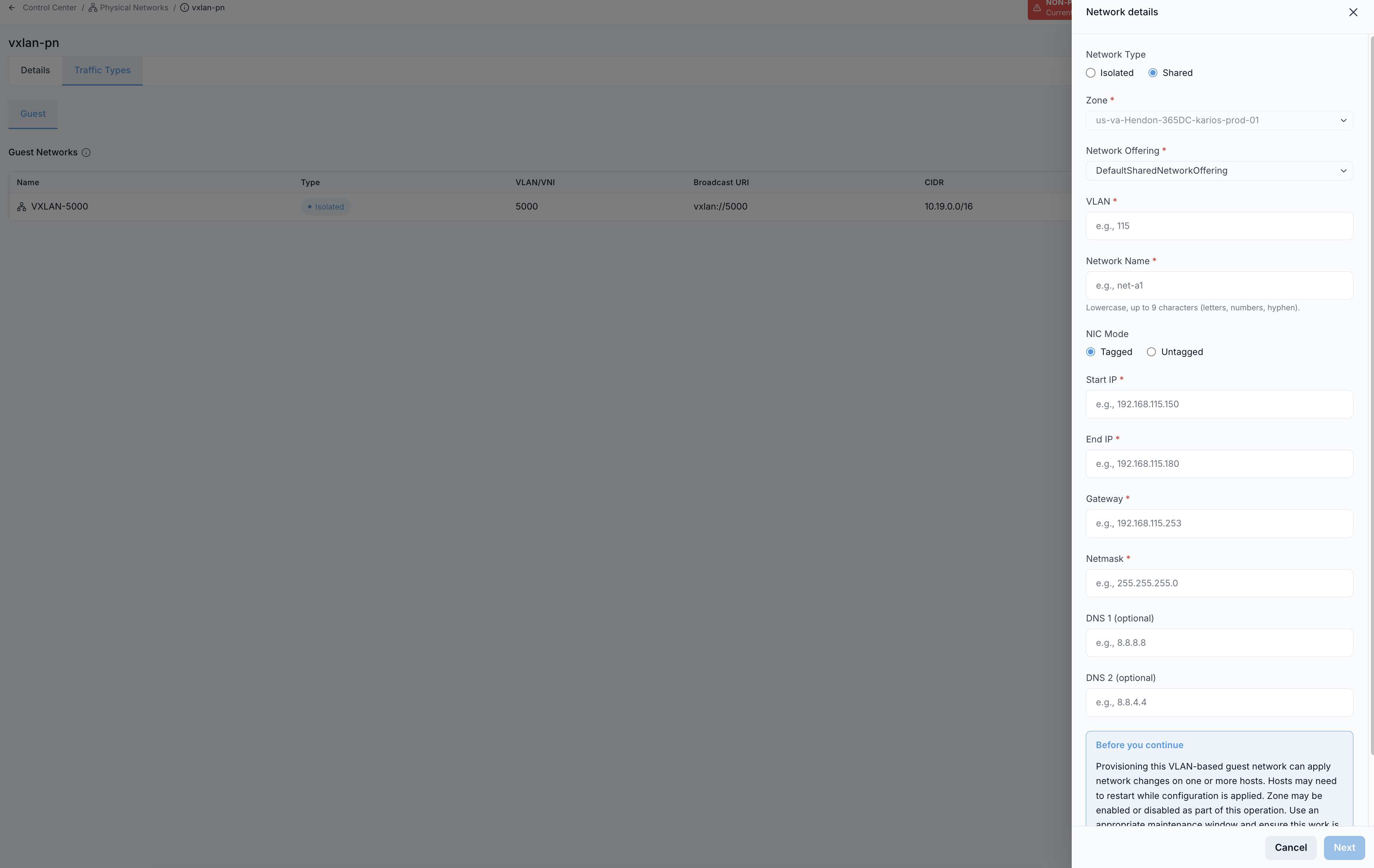
Step 1: choose Network Type as Shared.
Steps:
From
Traffic Types -> Guest, click+ Add Guest Network.Set
Network TypetoShared.Complete the required network details.
Click
Nextand complete the NIC assignment step, then clickCreate Network.
Shared-network fields:
Zone(required)Network Offering(required; must support shared networks)PVLAN Type(optional; defaults tonot a PVLAN)VLAN(required; oruntaggedwhere applicable)Network Name(required)NIC Mode:TaggedorUntaggedStart IPandEnd IP(required)Gateway(required)Netmask(required)DNSvalues when required by the environmentGuest MTU(optional)
Note
The shared-network IP range is the actual VM allocation pool. Size it for expected VM count.
Use the canonical field-level steps in Create Guest Network (Section 3.5).
Expected Outcome:
Network appears with state
Setupafter successful creation.Setupis the normal, operational state for a shared network - it is not an intermediate step waiting to becomeImplemented.VMs can consume IPs from the configured range.
Warning
Keep the gateway outside the VM allocation pool to avoid IP conflicts.
Warning
For shared networks, ensure VLAN is within the parent physical-network VLAN range (or use untagged when supported).
If this fails:
Follow the Create Guest Network shared-network failure checks first (subnet math, overlap, VLAN validity).
Confirm
Physical Network IDmatches the expected physical network.
Step: Open Guest Network Details
When to Use: Use this when you need full configuration for one guest network.
Purpose: The details page is the source for network configuration verification before attaching workloads.
Start from the Guest traffic details page shown in Task: Open Guest Traffic Details Page above.
Steps:
In
Traffic Types -> Guest, click a network name in theNamecolumn.Review full network configuration and attached workload context on the detail page.
Result page:
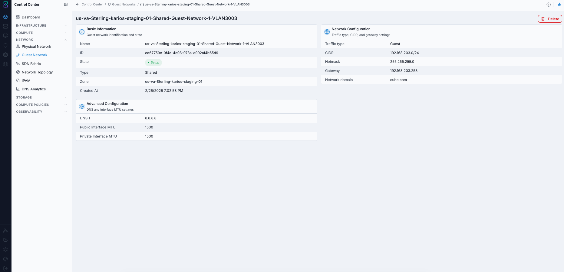
Expected Outcome:
The Guest Network details page opens.
You can review
Basic Information,Network Configuration, andAdvanced Configurationcards.
If this fails:
1. Verify the selected row exists in Traffic Types -> Guest.
2. Refresh and retry opening the same network row.
3. Confirm access rights for guest-network details.
Tips:
Use
Isolatedwhen tenant separation and NAT/firewall controls are required.Use
Sharedwhen workloads must be directly reachable on a common subnet.Network offering selection controls available services (DHCP, DNS, NAT, firewall, load balancing, VPN).
Management Traffic
Purpose:
Manage the internal control-plane network used by Karios infrastructure components.
Management traffic is the control plane for hosts, virtual routers, system VMs, and management services. Each management IP range is assigned per pod, and hosts consume IPs from the range of the pod they join.
Warning
Management IP exhaustion can block host onboarding and delay system-VM operations.
What Uses Management Traffic:
Hosts (KVM compute nodes)
Virtual Routers (network-service system VMs)
System VMs (for platform services)
Management Server control-plane communication
Management IP Ranges Table Columns:
Column |
Description |
|---|---|
Pod |
Pod this range belongs to. Pod name links to pod details. |
Zone |
Zone where the pod resides. |
Start IP |
First IP in the management range. |
End IP |
Last IP in the management range. |
VLAN |
VLAN tag or |
For System VMs |
Whether the range is reserved for system VMs only ( |
Step: Open Management Traffic Details Page
When to Use: Use this when reviewing control-plane IP ranges for a physical network.
Purpose: Management ranges determine addressing for hosts and system components in each pod.
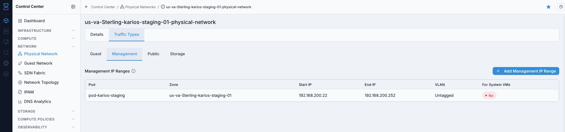
Details page shows:
A
Base Bridge · Management Trafficpanel naming the Linux bridge (for examplecloudbr0) this traffic type egresses on each host. This panel appears on every traffic-type tab; it readsNot setwhen the traffic type has no bridge label.Management IP range rows with pod, zone, subnet, VLAN, and system-VM reservation context.
+ Add Management IP Rangeaction for control-plane capacity expansion.
What you can do from this screen:
Review management addressing coverage per pod.
Add new management IP ranges.
Validate whether ranges are reserved for system VMs.
Steps:
Open
K-Nets -> Physical Network.Click the target physical network name.
Click
Traffic Types.Click
Management.
Expected Outcome:
You can review all management IP ranges for this physical network.
You can add ranges, validate pod assignment, and verify system-VM reservation settings.
Continue with Page Help Review:
Click the top-right help icon.
Use the
iicon besideManagement IP Rangesfor field definitions.For help-panel behavior, follow the same flow used in
2.2.1 Open Physical Network Help Panel.
If this fails:
Refresh and reopen
Traffic Types -> Management.Confirm the selected physical network row is correct.
Confirm your account can open traffic-type details pages.
Step: Add Management IP Range
When to Use: Use this when a pod needs additional management addressing capacity.
Purpose: Hosts and system services consume management IPs from pod-scoped ranges.
Steps:
Open
K-Nets -> Physical Network.Click the physical network name.
Click
Traffic Types -> Management.Click
+ Add Management IP Range.Fill required form fields:
Pod(required)Gateway(required)Netmask(required)Start IP(required)End IP(required)
Click
Create IP Range.
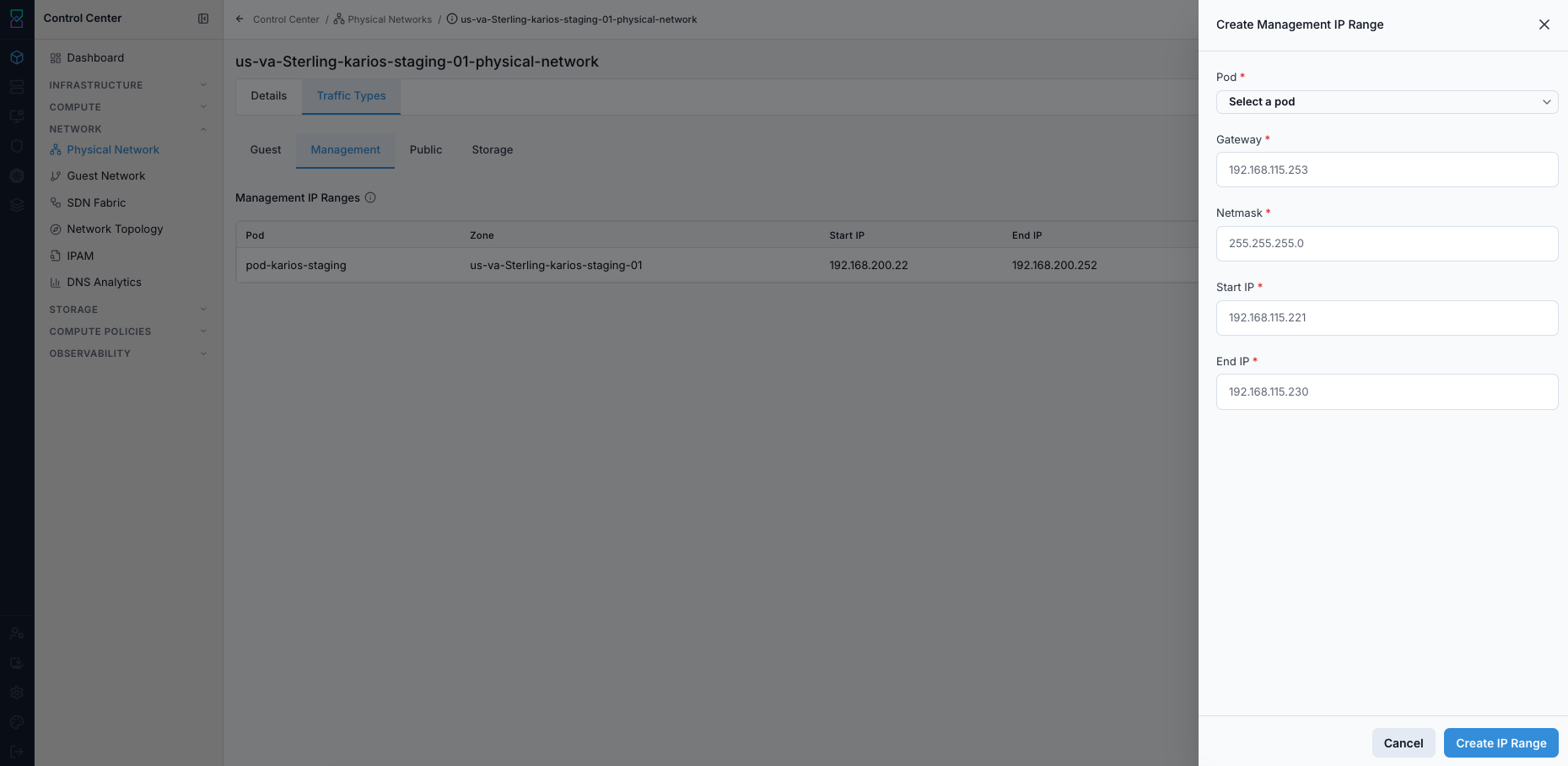
Field guidance:
Pod: only pods in the physical network’s zone are available.Gateway,Netmask,Start IP, andEnd IPmust be valid IPv4 values in the same subnet.Ensure
Start IP <= End IP.
Expected Outcome:
New row appears in
Management IP Rangesfor the selected pod.
How Many IPs to Plan:
One management IP per host added to the pod
Additional IPs for system VMs
Additional IPs for virtual routers when isolated guest networks are used
Tip
Allocate headroom in management ranges to avoid blocking future host or system-VM placement.
Warning
Do not overlap management range with guest, storage, or public ranges.
If this fails:
Verify pod selection is correct.
Verify IPv4 format and subnet math (gateway/start/end in same subnet).
Ensure
Start IP <= End IP.Confirm the range is not already present.
Management Tips:
Keep management traffic on a stable, dedicated network path.
Use pod-specific management ranges to avoid cross-pod conflicts.
Use
For System VMs: Yesranges when separating system-VM addressing from host management addressing.
Storage Traffic
Purpose:
Manage storage-network IP ranges used by hosts and storage services.
Storage traffic defines how hosts communicate with shared storage backends across Karios. These ranges are pod-scoped and are isolated on dedicated VLANs or subnets so storage I/O does not compete with management or guest traffic.
Warning
Running out of storage IPs can block new host onboarding and storage access expansion.
What Uses Storage Traffic:
Instance Storagebackends (for VM disk volume read/write paths)Image Storageservices (VM template, Boot Image, and snapshot transfer paths)Hoststhat mount and access shared storage
Storage IP Ranges Table Columns:
Column |
Description |
|---|---|
Pod |
Pod this storage range belongs to. |
Gateway |
Gateway for the storage subnet. |
Netmask |
Subnet mask for the storage subnet. |
Start IP |
First IP in the storage range. |
End IP |
Last IP in the storage range. |
VLAN |
VLAN tag for this range, or |
Note
The Storage IP Ranges table has no Actions column. Storage IP ranges are
platform-managed: deletion is intentionally not exposed in the UI, so an operator cannot
accidentally remove the storage networking the platform depends on. Storage ranges are
removed only through the platform teardown flow.
Step: Open Storage Traffic Details Page
When to Use: Use this when checking storage-network ranges on a physical network.
Purpose: Storage ranges are required for host-to-storage communication and expansion planning.
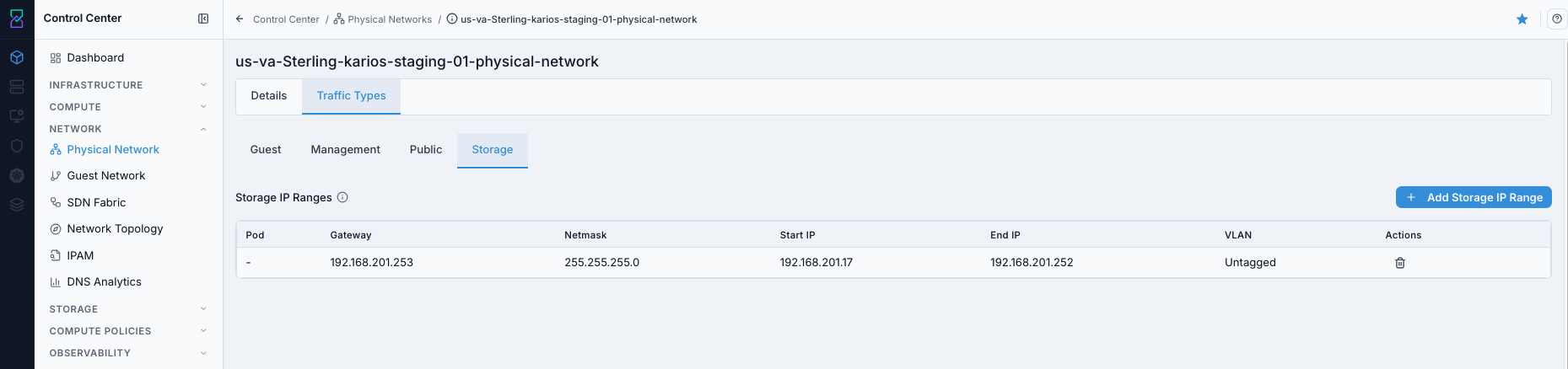
Details page shows:
A
Base Bridge · Storage Trafficpanel naming the Linux bridge (for examplecloudbr1) this traffic type egresses on each host. It readsNot setwhen the traffic type has no bridge label.Storage IP range rows with pod, subnet, and VLAN. There is no per-row action column.
+ Add Storage IP Rangeaction for storage-network capacity expansion.
What you can do from this screen:
Review storage network ranges per pod.
Add new storage IP ranges.
Steps:
Open
K-Nets -> Physical Network.Click the target physical network name.
Click
Traffic Types.Click
Storage.
Expected Outcome:
You can review storage ranges and launch the add action.
Continue with Page Help Review:
Click the top-right help icon.
Use the
iicon besideStorage IP Rangesfor field definitions.For help-panel behavior, follow the same flow used in
2.2.1 Open Physical Network Help Panel.
If this fails:
Refresh and reopen
Traffic Types -> Storage.Confirm the selected physical network row is correct.
Confirm your account can open storage traffic details.
Step: Add Storage IP Range
When to Use: Use this when a pod needs more storage-network IP capacity.
Purpose: Each host and storage service path consumes storage IPs from these ranges.
Steps:
Open
K-Nets -> Physical Network.Click the physical network name.
Click
Traffic Types -> Storage.Click
+ Add Storage IP Range.Fill required fields:
PodGatewayNetmaskStart IPEnd IP
Click
Create IP Range.
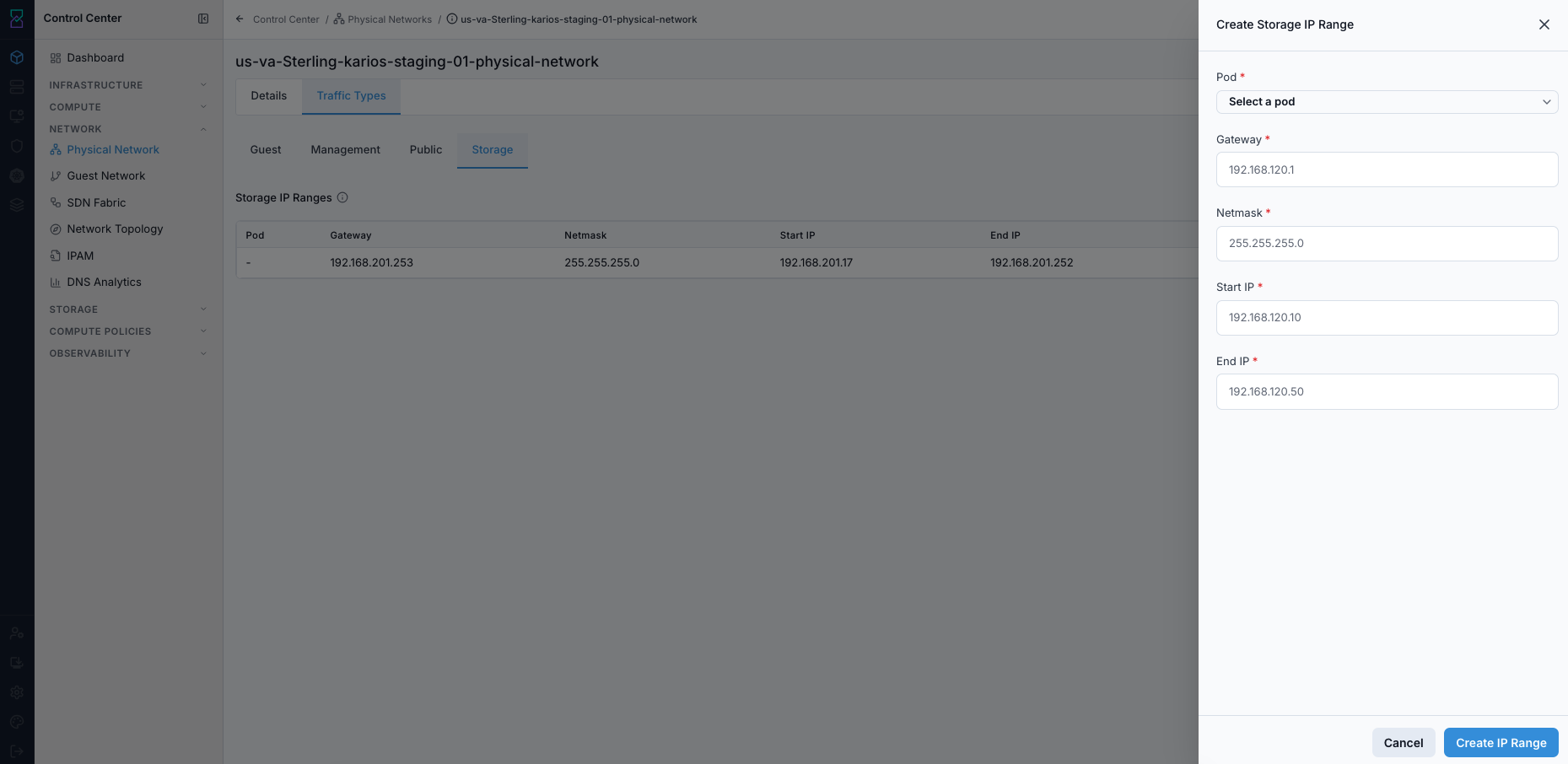
Field guidance:
Pod: choose the pod this range belongs to.Gateway,Netmask,Start IP, andEnd IPmust be valid IPv4 values in one subnet.Ensure
Start IP <= End IP.
Expected Outcome:
New row appears in
Storage IP Ranges.
How Many IPs to Plan:
One storage IP per host in the pod
One storage IP for image-storage services
Additional spare IPs for future host additions
Tip
Keep storage traffic on a dedicated low-latency network path where possible.
If this fails:
Confirm valid pod and subnet values.
Confirm no overlap with management/guest/public ranges.
Confirm
Start IP <= End IP.
Removing a Storage IP Range
There is no delete action for storage IP ranges in the UI. Storage IP ranges are platform-managed and are removed only through the platform teardown flow - deletion is deliberately withheld so an operator cannot remove the storage networking that hosts and image-storage services depend on.
If a storage range is wrong or too small, add a correctly sized range instead; existing hosts keep the IPs they already hold.
Storage Tips:
Use dedicated VLANs/subnets for storage traffic to protect storage performance.
Multiple storage ranges can exist in the same pod for separate storage backends.
Validate storage network bandwidth and latency to match backend requirements.
Public Traffic
Purpose:
Manage internet-facing IP ranges used for external connectivity services.
Public traffic provides the public IP inventory used for outbound and inbound connectivity in cloud networking workflows.
What Public IPs Are Used For:
Source NAT: outbound internet access for isolated guest networks.Static NAT: one-to-one public-to-private VM mapping.Port Forwarding: port-level mapping from public IP to VM service ports.Firewall: ingress policy control applied to public-IP traffic.Load Balancing: front-end public VIPs distributed to backend VM pools.VPN: remote-access and site-to-site tunnel endpoints.
Warning
Incorrect gateway or routing for public ranges can break all external connectivity for dependent services.
Public IP Ranges Table Columns:
Column |
Description |
|---|---|
VLAN |
VLAN tag for this range, or |
Gateway |
Upstream gateway for the public subnet. |
Netmask |
Subnet mask for the public range. |
Start IP |
First public IP in the range. |
End IP |
Last public IP in the range. |
Actions |
Edit and Delete controls for the range. |
Note
The edit and delete icons render only for accounts holding the NETWORK_MANAGE
permission. Without it the Actions cell is empty and the + Add Public IP Range
button is absent. The same permission gates the add action on every traffic type.
Step: Open Public Traffic Details Page
When to Use: Use this when reviewing internet-facing IP inventory and range actions.
Purpose: Public ranges back Source NAT, Static NAT, load balancer, VPN, and forwarding workflows.
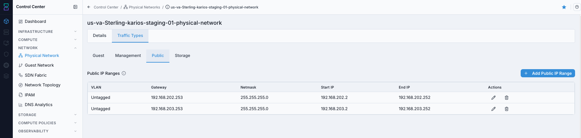
Details page shows:
A
Base Bridge · Public Trafficpanel naming the Linux bridge (for examplecloudbr2) this traffic type egresses on each host.Public IP range rows with
VLAN,Gateway,Netmask, and IP boundaries.Actionscolumn with pencil (edit) and trash (delete) icons per range.+ Add Public IP Rangeaction for expanding public inventory.
What you can do from this screen:
Review current public subnet inventory.
Add, edit, and delete public IP ranges.
Validate gateway/subnet consistency before NAT and exposure workflows.
Steps:
Open
K-Nets -> Physical Network.Click the target physical network name.
Click
Traffic Types.Click
Public.
Expected Outcome:
You can view configured public IP ranges and launch create/edit/delete actions.
Continue with Page Help Review:
Click the top-right help icon.
Use the
iicon besidePublic IP Rangesfor field definitions.For help-panel behavior, follow the same flow used in
2.2.1 Open Physical Network Help Panel.
If this fails:
Refresh and reopen
Traffic Types -> Public.Confirm the selected physical network row is correct.
Confirm your account can open public traffic details.
Step: Add Public IP Range
When to Use: Use this when you need additional public addresses for external connectivity services.
Purpose: Public IP pool size controls how many NAT, VPN, and public service mappings can be created.
Start from the Public traffic details page shown in Task: Open Public Traffic Details Page above.
Steps:
Open
K-Nets -> Physical Network.Click the physical network name.
Click
Traffic Types -> Public.Click
+ Add Public IP Range.Fill required fields:
Physical NetworkZoneGatewayNetmaskStart IPEnd IP
Optional:
VLAN- the VLAN ID, or leave blank/untaggedfor an untagged range.
Click
Create IP Range.
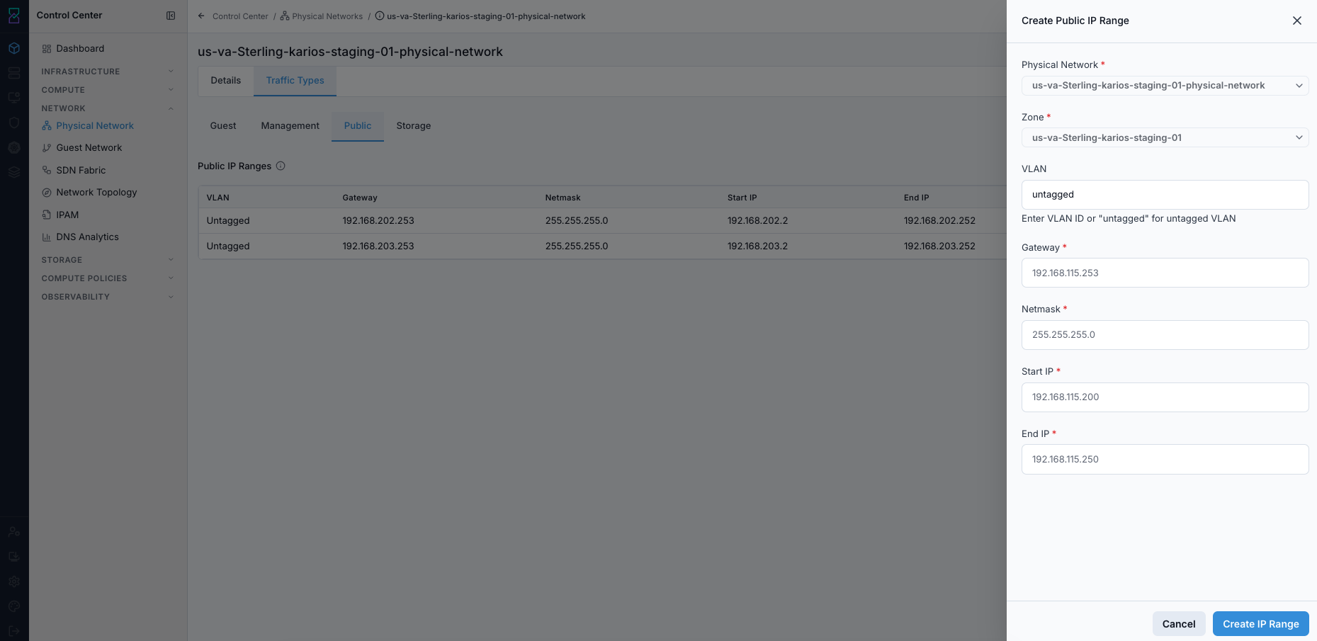
Field guidance:
Physical Network: parent network for this range.Zone: populated from the selected physical network.VLAN: tagged VLAN ID oruntagged.Gateway,Netmask,Start IP, andEnd IPmust be valid IPv4 values in the same subnet.
Expected Outcome:
New range appears in
Public IP Ranges.
How Many Public IPs to Plan:
One Source NAT IP per isolated guest network.
One IP per static NAT VM mapping.
Additional IPs for VPN and load-balancer endpoints.
Port-forwarding services can share a public IP when port mappings do not overlap.
If this fails:
Verify
Gateway,Netmask,Start IP, andEnd IPare valid and in the same subnet.Confirm range does not overlap an existing public range.
Confirm VLAN/tagging selection is valid for the selected physical network.
Step: Edit Public IP Range
When to Use: Use this when correcting gateway/netmask/start/end values on an existing range.
Purpose: In-place edits adjust usable public range boundaries without recreating the range object.
Start from the Public traffic details page shown in Task: Open Public Traffic Details Page above.
Steps:
In
Traffic Types -> Public, locate the target row.Click the pencil icon in
Actions.Update allowed fields in the edit form. All four are resubmitted together, so the form arrives pre-filled with the current values - change only what you need and leave the rest as-is.
Click
Update IP Rangeand verify the updated values in the table.
Expected Outcome:
Updated range values are visible in the
Public IP Rangestable.Existing allocations remain unchanged; only range boundaries/metadata are updated.
Tip
Use edit for boundary corrections; use new range creation for major subnet redesigns.
Editable fields:
GatewayNetmaskStart IPEnd IP
Not editable in-place (these are not shown on the edit form at all, not merely disabled):
VLANPhysical NetworkZone
Warning
Shrinking a range affects only unallocated IPs. In-use IP allocations are not reclaimed automatically.
If this fails:
Confirm you are editing allowed fields only (gateway/netmask/start/end).
Verify updated values remain in one valid subnet.
Refresh the page and retry the edit action.
Step: Delete Public IP Range
When to Use: Use this when a public range is no longer required.
Purpose: Removing unused ranges keeps the public IP inventory aligned to active services.
Start from the Public traffic details page shown in Task: Open Public Traffic Details Page above.
Steps:
In
Traffic Types -> Public, locate the target row.Click the trash icon in
Actions.Confirm deletion.
Refresh and verify row removal.
Expected Outcome:
The selected public IP range is removed from the table.
Deleted range space is no longer available for new allocation.
Warning
Delete is blocked when IPs are still allocated to NAT, load balancer, VPN, or forwarding rules.
If this fails:
Confirm subnet and gateway correctness.
Check whether any public IP from the range is in active use.
Validate you have sufficient privileges for the action.
Retry after releasing dependent public IP allocations.
Tips:
Public IPs are finite resources. Use port forwarding where possible to reduce one-IP-per-service consumption.
Multiple public ranges can be added to one physical network when needed.
Isolated networks consume public IPs for Source NAT; shared networks use their own guest-network IP definitions.
Always verify upstream gateway reachability before creating ranges.
→ Next: Guest Networks