VPCs
Use VPCs to create isolated, account-owned virtual networks with multiple subnets, built-in routing, firewall controls, load balancing, and optional VPN connectivity.
Note
Field-level guidance for each VPC form is in this page. VPC pages do not currently carry an inline ? help panel - use the field-guidance blocks in the sections below.
Typical first-time workflow:
Create a VPC (section 8.4) - define the zone, name, and IP supernet.
Add tiers (section 8.5) - create subnets inside the VPC for each workload layer.
Deploy VMs into tiers (section 8.6) - provision instances that receive IPs from tier CIDRs.
Acquire a Public IP (section 8.7.1) - pull an IP from the zone pool for inbound access.
Add rules - choose Static NAT (8.7.2), Port Forwarding (8.7.3), or Load Balancer (8.8.1) depending on your traffic pattern.
Apply Network ACLs (section 8.9) - control which traffic is allowed into or out of each tier.
Connect on-premises networks (section 8.10) - optional Site-to-Site VPN or Remote Access VPN.
8.1. What is a VPC?
A VPC (Virtual Private Cloud) is a private virtual network scoped to your account. It gives you:
Private IP space - a CIDR block you define, fully isolated from other VPCs.
Multiple subnets (“tiers”) inside it, each with its own CIDR and access policy.
Built-in router that handles east-west traffic between tiers and north-south traffic to the internet.
Stateful firewall for ingress and egress controls per tier.
Load balancers - public (internet-facing) and internal (east-west between tiers).
Public IP attach with NAT and port-forwarding rules.
Site-to-Site VPN to connect on-premises networks.
Remote Access VPN (L2TP / IPsec) for individual users to dial in from their devices.
Think of a VPC as a software-defined private datacenter with everything needed to host a multi-tier application in isolation.
8.2. VPC and Tier Offerings
8.2.1. VPC Offering
The create form presents a single VPC offering choice. Behind it, Karios composes the
CloudStack VPC offering from your Tier isolation, VR size, and Redundant VPC
selections, so the offering recorded on the VPC carries those attributes in its name:
Name |
Type |
Description |
|---|---|---|
Karios VPC (NAT’d) |
NAT’d + Static routing |
The default Karios VPC. Outbound NAT via the VPC router, public IPs attached on demand, public and internal load balancing supported inside. |
8.2.2. Tier Offerings
When creating a tier (subnet) inside the VPC, pick one offering based on what that tier serves.
On the Create Tier panel this choice is the Tier type field:
Tier Offering |
Best For |
What You Get |
|---|---|---|
Karios VPC Tier – Default |
Internet-facing tiers (web frontends, APIs) |
Public LB, Static NAT, Port Forwarding, VPN. VM AutoScaling where the offering enables it -
see section |
Karios VPC Tier – Hybrid |
Tiers that need an internal VIP AND the ability to attach a public IP (bastion, mixed backend) |
Internal LB + Static NAT, Port Forwarding, VPN. No Public Load Balancer. |
Karios VPC Tier – InternalLB |
Pure internal tiers (databases, internal microservices) |
Internal LB only - no public IP access by design |
Tip
Use the Tier Offering Selection Guide in section 8.12 to choose the right Tier type
for your topology before creating tiers.
8.3. VPC Dashboard
When to Use:
Use this as the entry point before creating, managing, or troubleshooting VPCs.
Purpose:
Review existing VPCs, check their state, and access create and detail actions.
Path:
Control Center -> Network -> VPCs
Dashboard shows:
Summary cards: Total VPCs, Operational, NAT / public edge, and Routed internal counts.
VPC table with columns: Name, CIDR, Mode, State, Zone.
+ Add VPCbutton (top-right) for new VPC creation.Per-row state badge - shows current VPC state (Enabled / Disabled).
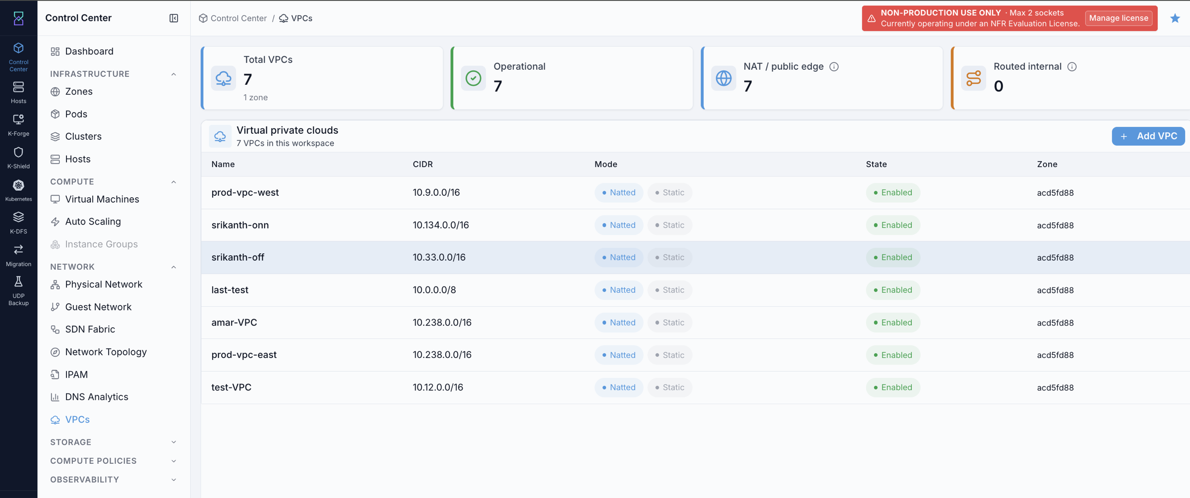
What you can do from this screen:
Click
+ Add VPCto open the create form.Click a VPC name to open the VPC detail page.
Review the VPC state (Enabled / Disabled) and mode (Natted) before making changes.
Expected Outcome:
You can identify existing VPCs, confirm their state, and proceed to create or manage actions.
If this fails:
See Common screen checks before retrying this screen.
8.4. Create a VPC
When to Use:
Use this when you need a new isolated virtual network for a workload or application group.
Purpose:
Create a VPC with a defined IP supernet, zone, and offering so tiers and VMs can be placed inside it.
Path:
Control Center -> Network -> VPCs -> Add VPC
Steps:
Open
Control Center -> Network -> VPCs.Click
+ Add VPC. The form opens showing the pre-selected Karios VPC (NAT’d) offering with its included services.Fill in the required fields:
Zone- the physical zone where this VPC is hosted.VPC Name- human-readable identifier (for exampleprod-east).VPC CIDR- the supernet for the VPC (for example10.0.0.0/16). Tiers will use sub-prefixes from this range. Enter the exact network address with host bits zero (10.0.0.0/16, not10.0.0.5/16) - Karios rejects a non-canonical CIDR with a validation error rather than normalising it.
Optional fields:
Redundant VPC- toggle on to run the VPC with a redundant router pair for higher availability. This is create-time only: redundancy is baked into the VPC offering that Karios composes at create time and cannot be turned on or off afterwards.Display Text- a friendly description shown in listings.Tier isolation-VLAN(tiers use VLAN tagging on the shared guest bridge) orVXLAN(tiers use VXLAN overlay segments instead).VR size- the router VM size (default: Medium, 2 vCPU / 1024 MB). Increase for high-traffic VPCs, or select+ New sizeunderCreate a custom VR sizeto define your own CPU/memory for tenants outside the standard small/medium/large tiers.
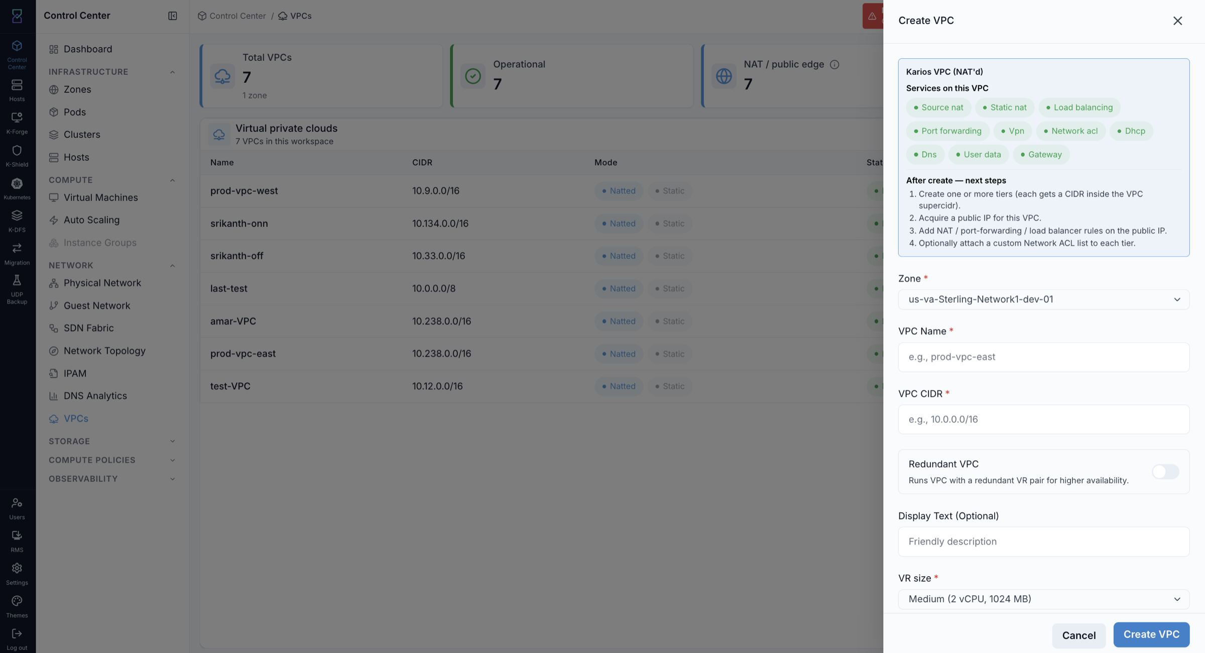
Click
Create VPC.
Field guidance:
VPC CIDR: choose a supernet that does not overlap your on-premises networks if you plan to use Site-to-Site VPN.VPC CIDRis immutable after creation - plan the supernet range before creating.Zone: a VPC is scoped to one zone. Cross-zone VPCs are not supported in the current release.
Expected Outcome:
The VPC appears in the VPCs table with state Enabled as soon as the create call returns.
The VPC router is requested automatically, but it is provisioned in the background and can take several minutes to boot. Enabled on the VPC row does not mean the router is up.
The VPC’s CIDR is registered in IPAM automatically.
Confirm on the
Routerstab that the router is Running before adding rules, then proceed to add tiers.
Clicking the VPC name opens the detail page:
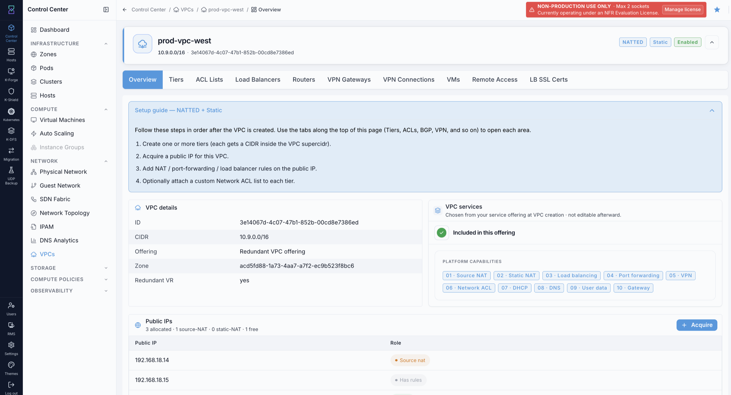
VPC detail page header badges (top-right):
NATTED - the VPC offering type.
Static - VPN/routing mode indicator.
Enabled - current VPC state.
VPC detail page tabs:
Overview - VPC summary, platform capabilities, public IPs at a glance, and a built-in 4-step quickstart guide.
Tiers - create and manage subnets inside the VPC.
ACL Lists - create and attach Network ACL lists to tiers.
Load Balancers - view, add, and manage both Public and Internal load balancer rules.
Port Forwarding - view and manage port-forwarding rules across the VPC’s public IPs.
Static NAT - view and manage 1-to-1 Static NAT mappings across the VPC’s public IPs.
Routers - view VPC router state, health, public IP, and redundancy role.
VPN Connections - provision the VPC’s local VPN endpoint and manage Site-to-Site VPN tunnels and customer gateways.
VMs - list all VMs deployed across all tiers in this VPC.
Remote Access - enable and manage the Remote Access VPN endpoint.
LB SSL Certs - upload and manage SSL certificates for TLS termination on Public LB rules.
The Routers tab confirms the VPC router was created automatically:
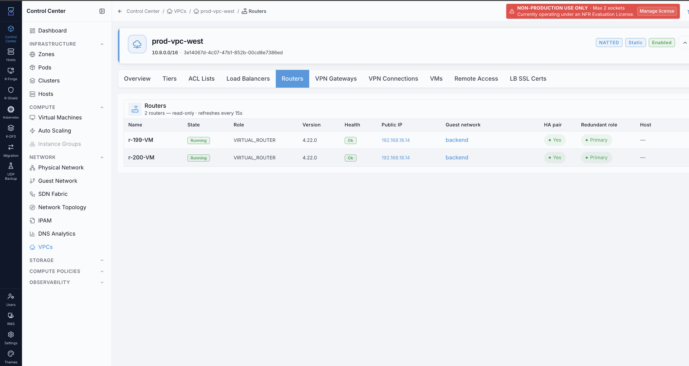
The Routers tab shows: router name, state, version, health, public IP, guest network, HA pair, and redundant role. This view is read-only - use it to verify the router is Running and OK before adding rules.
If this fails:
Confirm required fields are complete.
Confirm the CIDR is a valid RFC1918 IPv4 block and is canonical (host bits zero). VPC CIDRs are not checked for overlap against other VPCs - each VPC is independently isolated, so overlapping supernets are accepted.
Verify your account has permission to create VPCs in the selected zone.
Warning
VPC CIDR cannot be changed after creation. Choose the supernet carefully at create time.
8.5. Add a Tier
When to Use:
Use this to add a subnet inside an existing VPC for a specific workload tier.
Purpose:
Create a tier with the correct offering and CIDR so VMs in that tier get the right networking behavior.
Path:
Control Center -> Network -> VPCs -> [VPC name] -> Tiers tab -> Create Tier
Steps:
Open
Control Center -> Network -> VPCs.Click the target VPC name.
Click the
Tierstab.Click
Create Tier(top-right).Fill in the required fields:
Tier name- for exampleweb,app, ordb.Tier type- Default, Hybrid, or InternalLB (see section8.2.2).Gateway- the tier’s gateway address (for example10.20.1.1).Netmask- subnet mask (for example255.255.255.0for a /24).
There is no CIDR field. The tier’s CIDR is derived automatically from
Gateway+Netmask, and the derived prefix must fit inside the VPC supernet.Optionally, under
Network ACL, useChoose a listto attach an ACL list to the tier. See section8.9- attach a list explicitly rather than relying on a default.Click
Create Tier.
Note
If the VPC uses VXLAN tier isolation, each tier is a VXLAN overlay network and tier creation is gated on the SDN fabric being configured, rolled out, and BGP-established - exactly like a standalone VXLAN guest network. If the fabric is not ready the create is rejected before CloudStack is called. See SDN Fabric section 4.6, “When the Fabric Blocks Creation”.
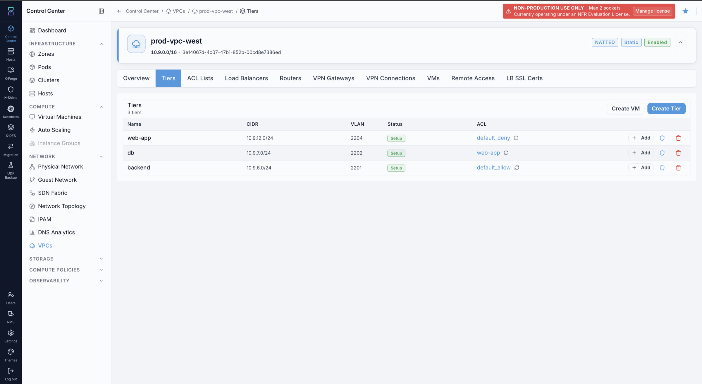
Tiers tab columns and actions:
Table columns: Name, CIDR, VLAN/VNI (auto-assigned; the header reads VNI for VXLAN-family VPCs), Offering (the tier offering), Status, ACL (attached ACL list name).
Tier status shows Setup. For Karios VPC tiers this is the normal steady state - it does not progress to Implemented, and waiting for it to change will not help. Judge tier readiness by the VPC router being Running on the
Routerstab, not by the tier status.Top-right buttons:
Create Tierto add another subnet;Create VMto deploy a VM directly into a tier from this tab.Per-tier row actions:
Edit (pencil icon) - update the tier name or ACL.
Delete (trash icon) - remove the tier. The tier must have no VMs before it can be deleted.
Add (
+ Addbutton) - attach or change the ACL list assigned to that tier.
Field guidance:
Gateway+Netmask: the CIDR they imply must be inside the VPC supernet and must not overlap any existing tier.A VPC supports up to 3 tiers by default.
Typical pattern:
web(Default),app(Hybrid or InternalLB),db(InternalLB).
Expected Outcome:
The tier appears under the
Tierstab with the selected offering and CIDR.VMs can now be deployed into this tier.
If this fails:
Confirm the tier CIDR is within the VPC supernet and does not overlap an existing tier - the error message will name the conflict.
Confirm required fields are complete and valid.
Verify your account has permission to modify the selected VPC.
8.6. Deploy a VM into a Tier
When to Use:
Use this when you are ready to place a VM inside a VPC tier.
Purpose:
Provision a VM that receives an IP from the selected tier’s CIDR and uses the VPC router for outbound traffic.
Steps:
Open the VPC detail page, click the
Tierstab, and clickCreate VM(top-right), or go toControl Center -> Compute -> Virtual Machinesand clickCreate VM- then select the VPC tier from theNetworkfield in the form.In the Provision Virtual Machine form, fill in the required fields. In the
Networkfield, select the target VPC tier.Click
Provision VM.
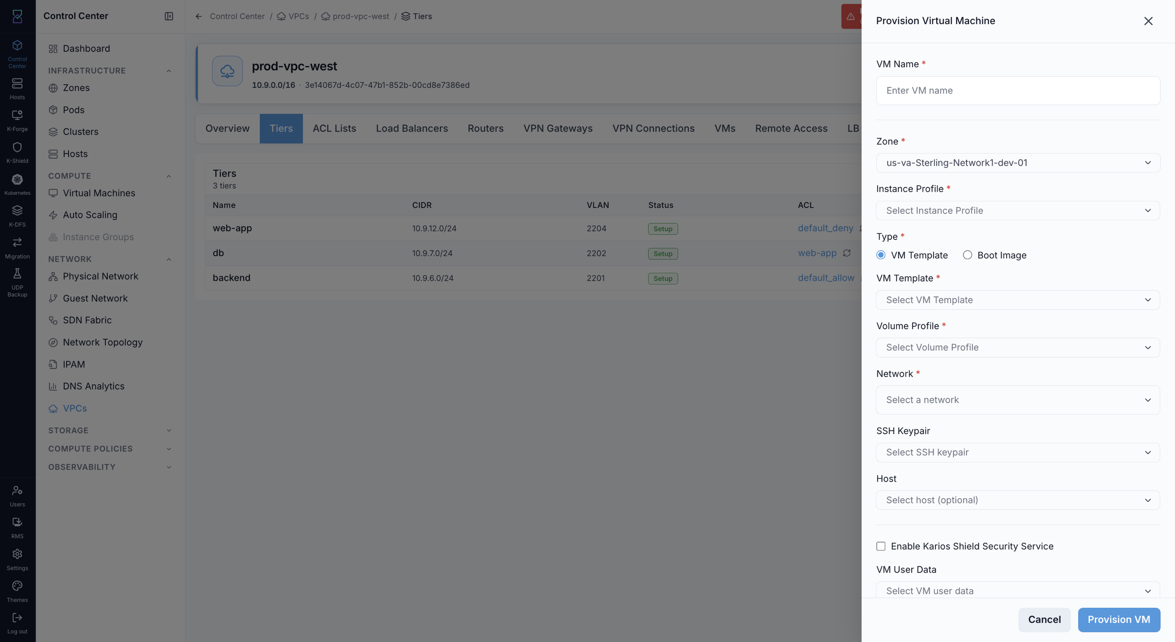
What the VM gets:
An IP from the tier’s CIDR (auto-assigned, or you can pin a specific address).
A NIC attached to the VPC router.
Outbound internet access via the VPC router’s Source NAT - no public IP required for outbound-only traffic.
Expected Outcome:
The VM appears in the
VMstab of the VPC with a private IP from the tier’s CIDR and state Running.The VM can reach the internet outbound via Source NAT without needing a public IP.
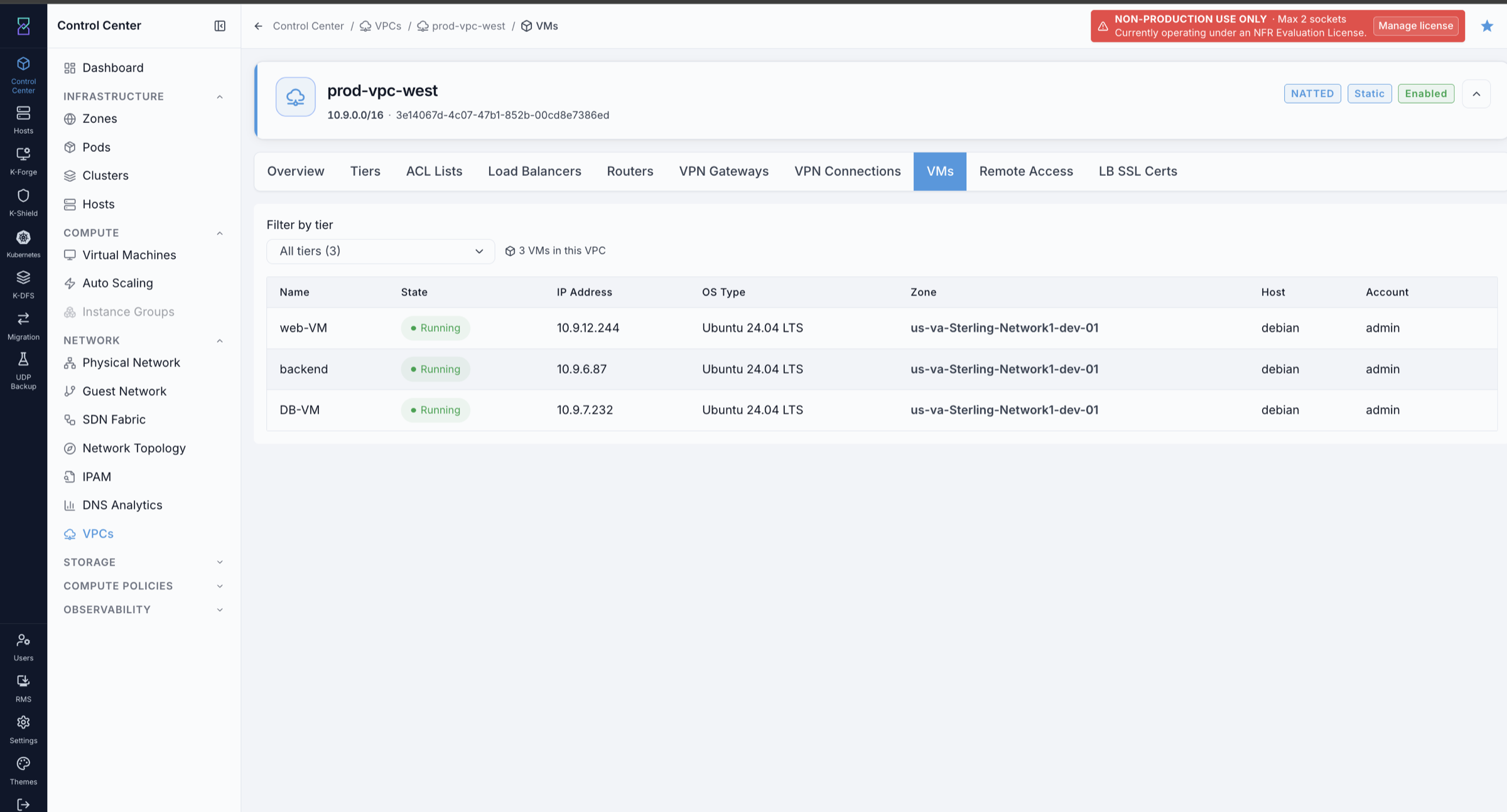
If this fails:
Confirm the selected tier exists and is in state Setup (the normal steady state for a Karios VPC tier), and that the VPC router is Running on the
Routerstab.Confirm the VM template and service offering are available in the zone.
Check the Events log for provisioning errors.
See also
For full VM creation steps, use Compute - Virtual Machines.
8.7. Public IPs
Public IPs give VMs in internet-facing tiers inbound connectivity via the VPC router. A public IP is VPC-scoped - it is not assigned to a tier until you create the first rule on it (Static NAT, Port Forwarding, or Load Balancer).
8.7.1. Acquire a Public IP
When to Use:
Use this when a tier needs a public IP for inbound access (Static NAT, Port Forwarding, or Load Balancer).
Purpose:
Pull a public IP from the zone pool and attach it to the VPC so you can create rules on it.
Path:
Control Center -> Network -> VPCs -> [VPC name] -> Overview tab -> Public IPs section
Steps:
Open the VPC detail page. The Overview tab shows the Public IPs section at the bottom, listing all IPs currently acquired for this VPC.
Click
Acquire(top-right of the Public IPs section).Read the confirmation dialog and click
Acquire. Once the IP is allocated the dialog shows it underAcquired; clickDoneto close.
Expected Outcome:
The new IP appears in the Public IPs section with no rules attached yet.
Click the IP address or Add rules to open its detail page and create rules (Static NAT, Port Forwarding, or Load Balancer).
If this fails:
Confirm public IPs are available in the zone’s public pool.
Confirm your account has permission to acquire public IPs.
Refresh the
Public IPstab and retry.
8.7.2. Static NAT
When to Use:
Use this when one VM needs its own dedicated public IP - for example, a bastion host or a single-server service.
Purpose:
Create a 1-to-1 mapping between a public IP and one VM so all inbound traffic to that IP goes directly to that VM.
Path:
Control Center -> Network -> VPCs -> [VPC name] -> Overview tab -> Public IPs section -> [IP address] -> Static NAT
Steps:
In the Public IPs section on the Overview tab, click the target IP address to open its detail page.
Click
Static NAT.Select the target tier from the dropdown - only tiers with eligible VMs are shown.
Pick the target VM. The VM’s NIC address is auto-filled from the selected NIC.
Click
Enable Static NAT.
Expected Outcome:
The public IP detail page shows Static NAT as Enabled with the selected VM listed.
All inbound traffic to the public IP is forwarded to that VM on all ports.
The VM can also send outbound traffic through this public IP.
Note
Static NAT does not bypass the tier’s Network ACL. The ACL list attached to the tier still filters this traffic - if inbound connections do not arrive, check the ACL before the NAT mapping.
If this fails:
Confirm the target VM is in a Default or Hybrid tier - InternalLB tiers do not support Static NAT.
Confirm the selected public IP does not already have a Port Forwarding or Load Balancer rule. Static NAT is exclusive: an IP that already carries Port Forwarding or Load Balancer rules cannot have Static NAT enabled, and an IP with Static NAT cannot take Port Forwarding or Load Balancer rules. Port Forwarding and Load Balancer rules can share one IP with each other, as long as their port ranges do not overlap.
8.7.3. Port Forwarding
When to Use:
Use this when one public IP needs to serve multiple VMs on different ports - for example, port 22 goes to a bastion, port 80 goes to a web VM.
Purpose:
Map specific public port ranges on a public IP to specific VMs and ports.
Path:
Control Center -> Network -> VPCs -> [VPC name] -> Overview tab -> Public IPs section -> [IP address] -> Port Forwarding
Steps:
In the Public IPs section on the Overview tab, click the target IP address to open its detail page.
Click
Port Forwarding.In the
Create new port forwarding rulepanel, fill in:Tier- the tier holding the target VM. On an IP that is already bound to a tier this is fixed.Port type- single port or a range.Public port- the port exposed on the public IP. In range mode the field splits intoPublic port (start)and(end).Private port- the corresponding port on the target VM. In range mode a port range is forwarded 1:1, so the private range mirrors the public range and cannot be remapped.Protocol- TCP or UDP.Source CIDR- the client range allowed to use this rule.Attached VM- pick the backend VM.
Click
Create rule.
Expected Outcome:
The rule appears in the Port Forwarding list.
Traffic arriving on the public IP at the specified port is forwarded to the target VM’s private port.
Multiple rules can be added on the same public IP for different VMs or ports.
If this fails:
Confirm the target tier is Default or Hybrid - InternalLB tiers do not support Port Forwarding.
Confirm the rule does not conflict with an existing rule on the same public IP. Two rules only clash when the port ranges overlap and the protocol is the same and the source CIDR is the same - rules that differ on any one of those can coexist on the IP.
Confirm the public IP does not have Static NAT enabled - Static NAT and Port Forwarding cannot share an IP.
8.8. Load Balancing
8.8.1. Public Load Balancer
When to Use:
Use this when you need to distribute internet traffic across multiple VMs in a Default tier.
Purpose:
Create an internet-facing load balancer rule on a public IP, targeting a pool of VMs in the tier.
Path:
Control Center -> Network -> VPCs -> [VPC name] -> Load Balancers tab
The Load Balancers tab shows a summary bar (Total Rules, Backends, Public IPs, Internal VIPs, Tiers) and lists Public Load Balancers and Internal Load Balancers in separate sections.
Steps:
Open the VPC detail page and click the
Load Balancerstab.In the Public Load Balancers section, click
+ Add Public LB.Configure the rule:
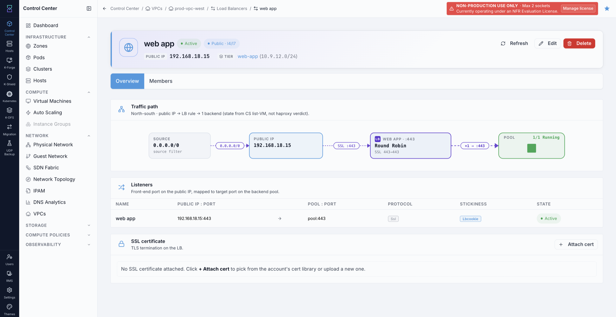
Name- and, optionally,Description.VPC- fixed when the rule is created from inside a VPC.Public IP- the acquired IP this rule listens on.Tier (backend targets)- the tier holding the backend VMs.Public port- the port exposed on the public IP.Private port- the port on the backend VMs.Algorithm- Round-robin, Least connections, or Source.Protocol-TCPfor passthrough,SSL (TLS termination)to terminate TLS at the load balancer, orTCP proxy (preserve client IP). Selecting SSL adds a requiredSSL certificatefield - upload the certificate first (see below).Source CIDR list- client CIDRs allowed to hit this rule.0.0.0.0/0allows any source.
Click
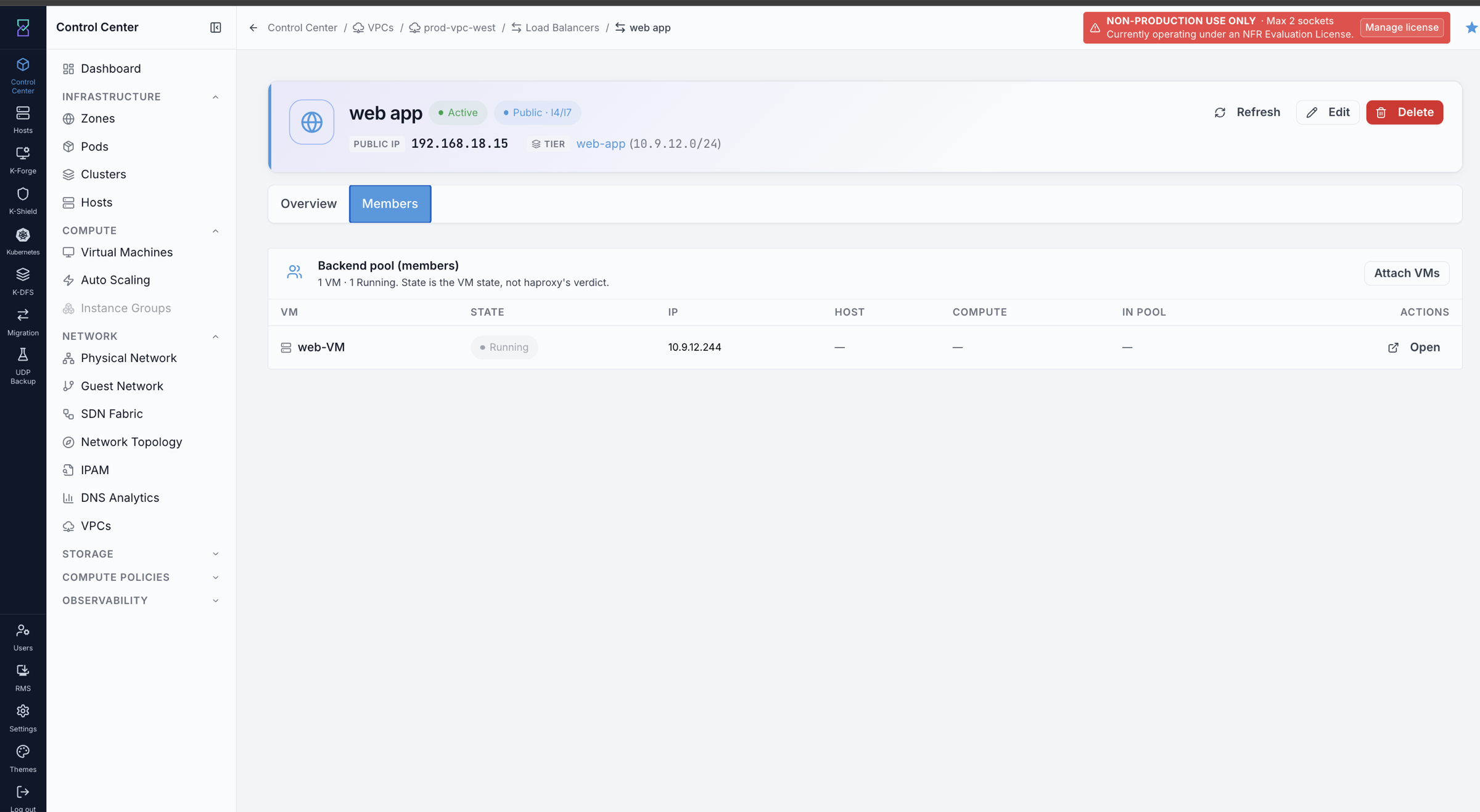
Create rule. Then open the rule, go to itsBackend pooltab, and clickAttach VMsto add backend VMs from the selected tier.
Warning
Do not attach VMs manually to a rule you intend to use with AutoScale. AutoScale manages
pool membership itself and is rejected on any rule that has ever had a VM binding. See
section 8.11.
Load balancer rules list:
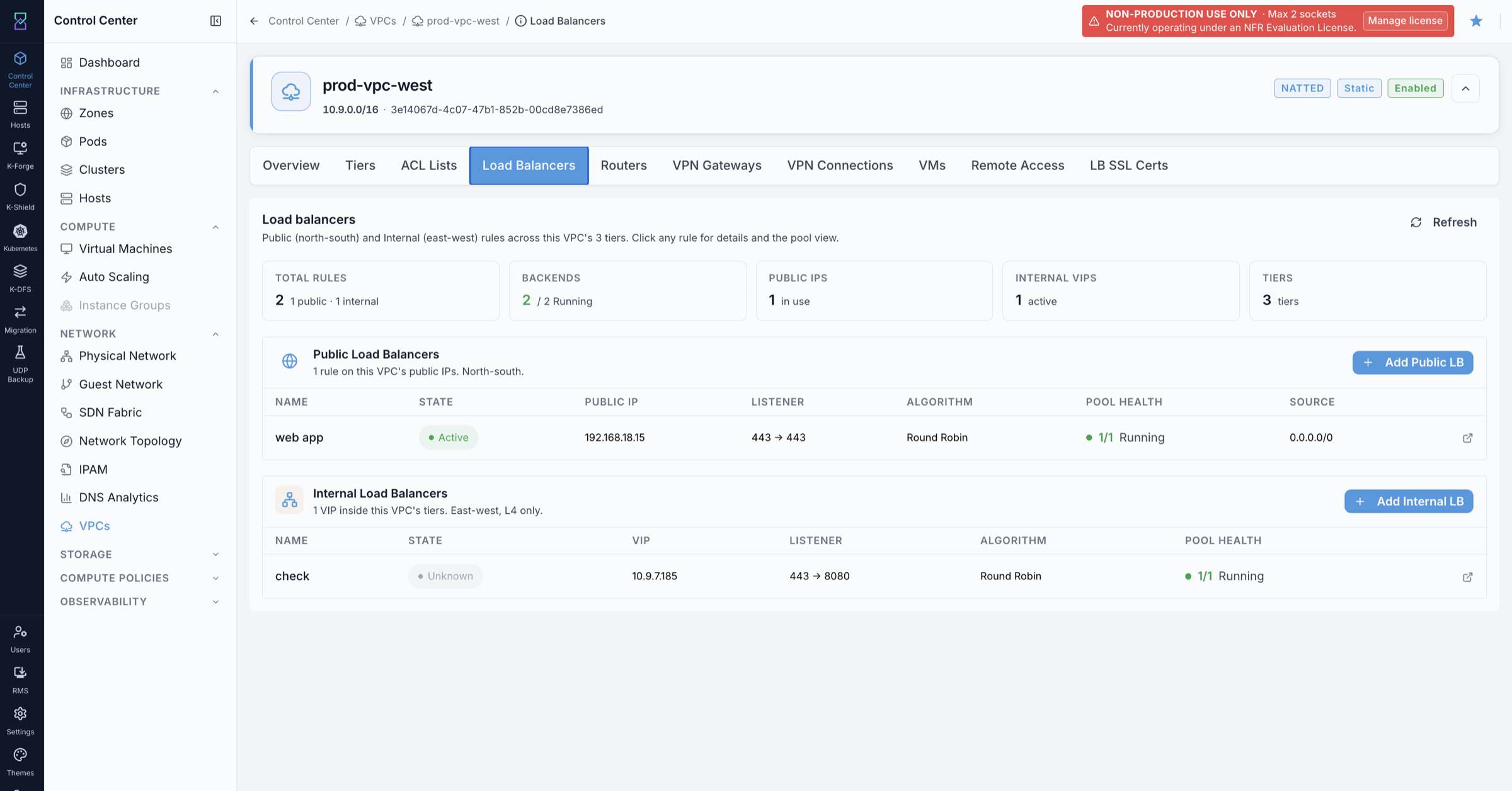
Rule configuration - port, protocol, and algorithm:
Backend members - VMs added to the pool:
Optional settings:
Stickiness - session affinity to keep a client on the same backend VM. Click Update in the Stickiness column of the Listeners section to configure.
SSL termination - terminate HTTPS at the load balancer by attaching a certificate. See below.
Multiple listeners - multiple port rules can be added to the same LB rule via the Listeners section.
SSL certificate workflow:
SSL certificates are managed at the VPC level on the LB SSL Certs tab, then attached to individual LB rules.
To upload a certificate:
Open the VPC detail page and click the
LB SSL Certstab.Click
+ Upload SSL Certificate.Fill in the fields:
Name- a label for this certificate (for examplewildcard-prod-2026).Certificate (PEM)- paste the full certificate in PEM format.Private key (PEM)- paste the private key. The key is write-only and never returned after upload.Certificate chain (PEM, optional)- paste concatenated intermediate certificates, root last.
Click
Upload.
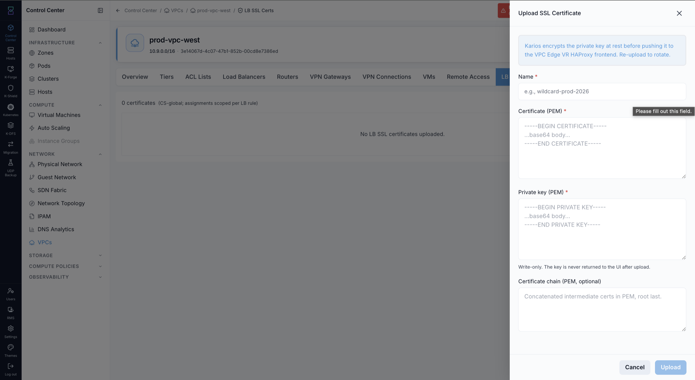
To attach the certificate to an LB rule:
Open the LB rule from the Load Balancers tab.
In the SSL certificate section on the rule’s Overview tab, click
Attach cert.Select the uploaded certificate from the list.
Expected Outcome:
Inbound traffic to the public IP on the configured port is distributed across the backend VM pool.
If this fails:
Confirm the tier is Default - Public LB is not available on InternalLB tiers.
Confirm VMs are running and are in the same tier as the LB rule.
Confirm the public IP is not already bound to a Static NAT rule.
Note
The rule is applied as part of the API job - it either succeeds or fails, there is no separate propagation window. If the job reports success and traffic still does not arrive, check the tier’s Network ACL and confirm the VPC router is Running.
8.8.2. Internal Load Balancer
When to Use:
Use this when backend services need a VIP for service-to-service traffic within the VPC (not internet-facing).
Purpose:
Create an internal-only VIP on a Hybrid or InternalLB tier so services can reach a stable address regardless of which VM handles traffic.
Path:
Control Center -> Network -> VPCs -> [VPC name] -> Load Balancers tab
Steps:
Open the VPC detail page and click the
Load Balancerstab.In the Internal Load Balancers section, click
+ Add Internal LB.Fill in the rule fields:
Name- a label for this internal LB rule.Tier (VIP + backends)- the Hybrid or InternalLB tier that hosts the VIP and its backends.Source port- the port exposed on the VIP.Backend port- the port on the backend VMs.Algorithm- Round-Robin, Least Connections, or Source IP Hash.VIP address- leave onAuto-allocate from tier CIDR (recommended), or chooseSpecific addressand enter an address inside the tier’s CIDR.
There is no
Protocolfield on an internal load balancer. Internal LB is TCP only.Click
Create. Then open the rule, go to itsBackend pooltab, and clickAttach VMsto add backend VMs from the same tier to the pool.
Expected Outcome:
The internal LB rule appears in the tier’s Internal LB list with the configured VIP and port.
VMs in the VPC can reach the VIP address and traffic is distributed across the backend pool.
Note
The InternalLB system VM is deployed lazily, on the first member assignment. The VIP only becomes active once that system VM is Running, which takes a short time after you attach the first backend.
If this fails:
Confirm the tier offering is Hybrid or InternalLB - Default tiers do not support Internal LB.
Confirm the backend VMs are running and in the same tier as the rule.
If you chose
Specific address, confirm theVIP addressis within the tier’s CIDR range.
8.9. Network ACLs
When to Use:
Use this to control which traffic is allowed into or out of a tier.
Purpose:
Apply ingress and egress rules at the tier level to enforce security policy.
Path:
Control Center -> Network -> VPCs -> [VPC name] -> ACL Lists tab
Steps:
Open the VPC detail page and click the
ACL Liststab. The tab shows all ACL lists for this VPC, including two built-in lists: default_allow (allow all) and default_deny (deny all). These cannot be deleted.Click
+ Create ACL List, fill inList name(for exampleweb-tier-acl) and an optionalDescription, then clickCreate ACL.Click the ACL list name to open it, then click
+ Add Ruleand fill in theAdd ACL Rulepanel:Action- Allow or Deny.Direction- Ingress (inbound to tier) or Egress (outbound from tier).Protocol- TCP, UDP, ICMP, or All.Rule number (optional)- position in the list; leave blank to append.Source CIDR list (optional)- the IP ranges the rule applies to.Start port/End port- port or port range (for TCP/UDP rules).ICMP type/ICMP code- for ICMP rules only.Reason (optional)- a label for this rule.
Click
Add ruleto save it. Built-in lists (default_allow,default_deny) are system-managed and cannot have rules added, edited, reordered, or removed.After adding rules, go back to the
Tierstab. In the target tier row, click the+ Addbutton and select the ACL list to attach it.
ACL Lists tab row actions:
Edit (pencil icon) - rename the ACL list.
Delete (trash icon) - remove the ACL list. Built-in lists (default_allow, default_deny) cannot be deleted.
Remove - detach the ACL list from a tier (shown in the Attached tiers column).
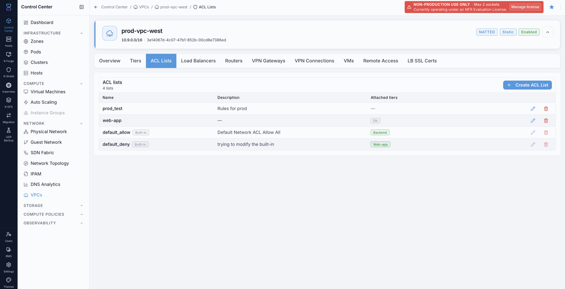
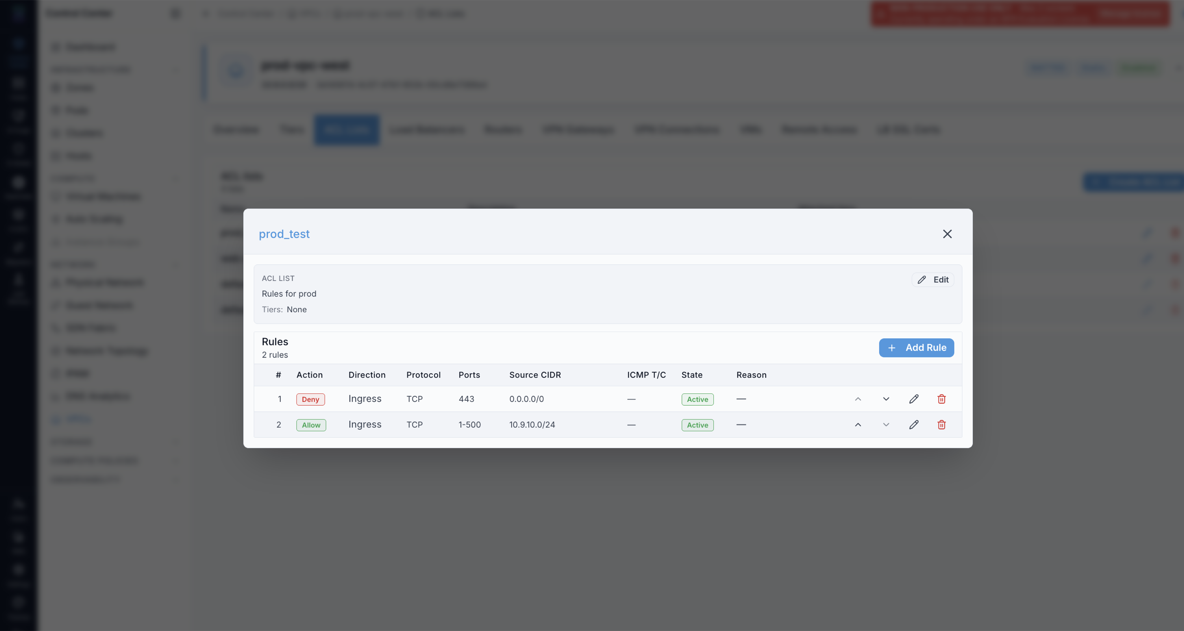
Key behavior:
ACL lists are reusable - one list can be attached to multiple tiers.
Different tiers can have different ACL lists (different security postures per tier).
Attach an ACL list explicitly. A tier created without one has no ACL list recorded against it - the Create Tier panel omits the field entirely when you leave the dropdown on its default, so no list is programmed. Attach
default_denyand then add allow rules, or attach a custom list, rather than relying on an implied default posture.Rules are evaluated in order - first match wins.
Expected Outcome:
The tier accepts or rejects traffic according to the ACL rules in the attached list.
If this fails:
Confirm the ACL list is attached to the correct tier.
Review rule order - a deny rule earlier in the list blocks traffic before a later allow rule is evaluated.
Confirm the protocol, port range, and CIDR in the rule match the expected traffic.
8.10. Site-to-Site VPN
When to Use:
Use this to connect an on-premises network to the VPC so on-premises hosts can communicate with VMs in VPC tiers.
Purpose:
Create an encrypted tunnel between the VPC and an on-premises firewall or VPN device.
Site-to-Site VPN is managed entirely on the VPN Connections tab. Complete the steps in order.
Step 1 - Provision the VPC’s local endpoint
Path: Control Center -> Network -> VPCs -> [VPC name] -> VPN Connections tab
Open the VPC detail page and click the
VPN Connectionstab. The Local endpoint shows the VPC’s source-NAT public IP - this is the Karios side of the tunnel.If the local endpoint is not yet provisioned, click
Provisionto create it on the VPC’s source-NAT IP.

Step 2 - Add a Customer Gateway and Connection
Path: Control Center -> Network -> VPCs -> [VPC name] -> VPN Connections tab
Click the
VPN Connectionstab.In the Customer gateways (peers) section, click
Add Customer Gateway.Fill in the remote on-premises endpoint details (public IP and remote CIDR).
Click
Add Connectionto create the tunnel between the VPC gateway and the customer gateway.Confirm the tunnel state in the S2S VPN connections section.
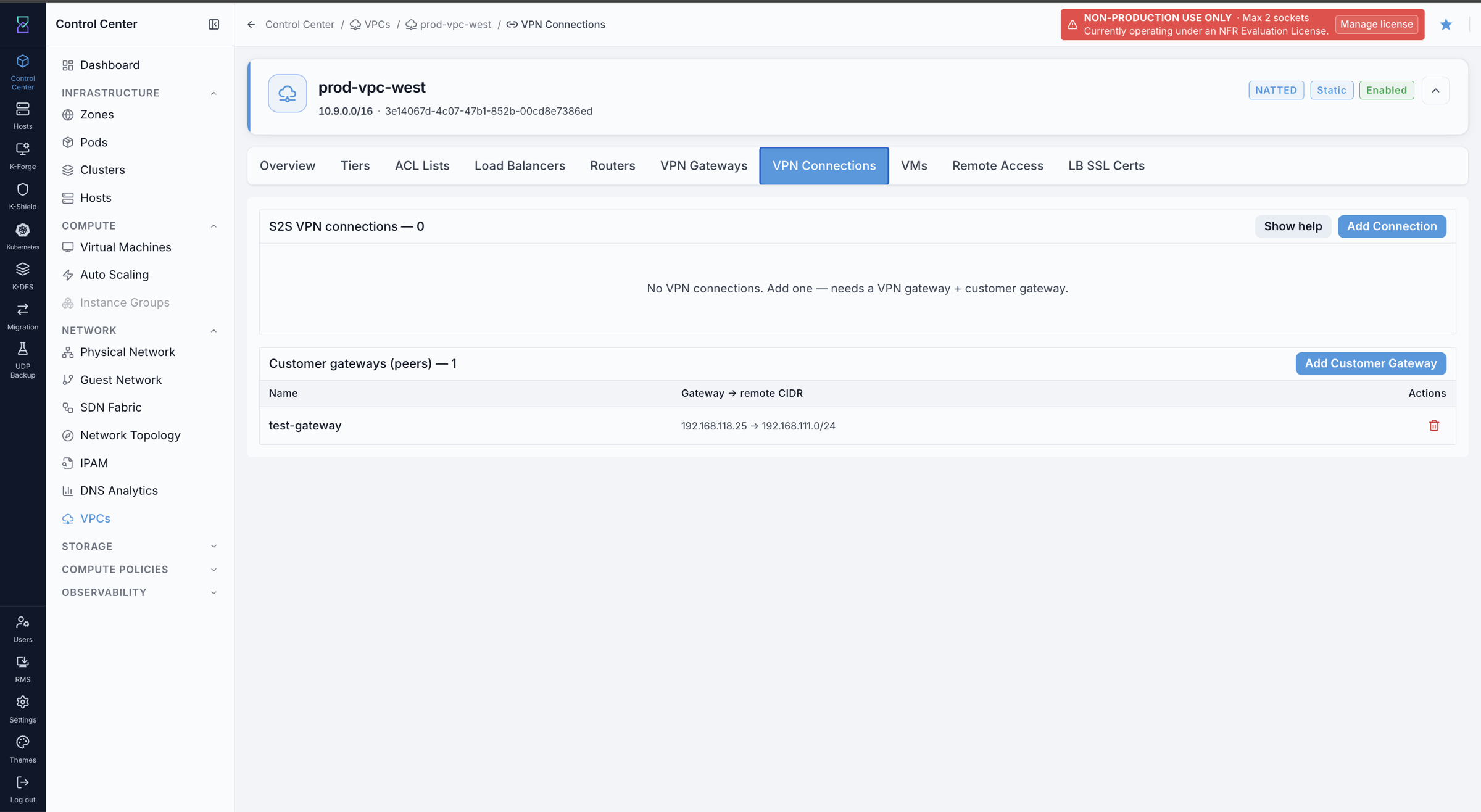
Expected Outcome:
The S2S VPN connection appears in the list with an active state.
On-premises hosts can reach VMs in the VPC tiers over the tunnel.
If this fails:
Confirm the customer gateway public IP and remote CIDR are correct.
Confirm the VPC CIDR does not overlap the on-premises network CIDR.
Review the connection status for negotiation errors - the status field shows the current phase.
8.10.1. Remote Access VPN (L2TP / IPsec)
When to Use:
Use this when individual users need to dial in to the VPC from their device - not for connecting entire on-premises networks (use Site-to-Site VPN for that).
Purpose:
Enable a per-user L2TP/IPsec VPN endpoint on the VPC so remote users can reach VMs inside the VPC.
Compatible clients: macOS, Windows, iOS, Android, strongSwan / xl2tpd on Linux - all using the native L2TP/IPsec VPN client built into the OS.
Path:
Control Center -> Network -> VPCs -> [VPC name] -> Remote Access tab
Prerequisite:
The VPC must have a Source NAT public IP already acquired. The Remote Access endpoint is bound to this IP. If no source NAT IP exists, acquire one first from the
Public IPstab - the Enable RAS button will be unavailable until this is done.
Steps - Enable the RAS server:
Open the VPC detail page and click the
Remote Accesstab.In the RAS server section, click
Enable RAS.Note the public IP and the auto-generated pre-shared key (PSK) that appear after enabling.
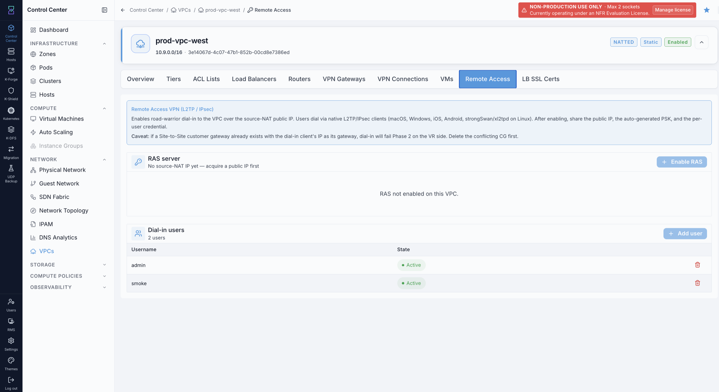
Steps - Add dial-in users:
In the Dial-in users section, click
Add user.Enter the username and password for the user.
Share the public IP, PSK, username, and password with the user so they can configure their VPN client.
Expected Outcome:
RAS server section shows the VPN as enabled with the public IP and PSK.
Dial-in users section lists added users with state Active.
Users can connect using the L2TP/IPsec client on their device with the public IP, PSK, and their credentials.
If this fails:
Confirm the VPC has a Source NAT public IP - the Enable RAS button is unavailable without one.
Confirm the VPC router is in state Running (check the Routers tab).
If a user cannot connect: verify the public IP, PSK, and credentials are correct.
Only one Remote Access VPN can exist per public IP - if enabling fails, check whether one is already configured on the VPC’s Source NAT IP.
8.11. AutoScale
When to Use:
Use this when a public-facing tier needs to automatically add or remove VMs based on load.
Purpose:
Attach an AutoScale VM group to an existing Public Load Balancer rule so the VM count behind that rule adjusts automatically.
Requirements:
A Public Load Balancer rule must already exist. AutoScale is a Public-LB feature; internal load balancers cannot drive it.
That LB rule must have no VM bindings at all. AutoScale manages pool membership itself and CloudStack refuses to attach a group to a rule that has ever had a VM bound to it - including a leftover or pending binding that no longer appears in the rule’s member list. Use a freshly created rule that you have never run
Attach VMsagainst (see the warning in section8.8.1).The rule’s tier must sit on a network offering that has VM AutoScaling enabled. The
Networkdropdown in the create form lists only networks whose offering supports it - if your tier does not appear there, its offering does not carry the capability. Confirm with your platform administrator which tier offerings are AutoScale-enabled in your zone.Only one AutoScale group can be attached to a given LB rule.
Path:
Control Center -> Compute -> Auto Scaling
Steps:
Open
Control Center -> Compute -> Auto Scalingand start a new AutoScale VM group.Choose the
Zone, then theTemplateandCompute Offeringused for new instances.Give the group a
Nameand setMin VM's/Max VM'sand thePolling Interval (s).Select the
Network- only AutoScale-capable networks are listed. Pick it first; the rule list below is filtered to that network.Select the
Load Balancer Rulethe group will manage.Configure the scale-up and scale-down policies - counter, operator, threshold, duration, and quiet time.
Save the group.
Expected Outcome:
New VMs are provisioned automatically when scale-up conditions are met and removed when scale-down conditions are met. Membership of the LB rule is managed by the group from this point on - do not attach VMs to that rule by hand.
If this fails:
If the create is rejected because the rule still has VM bindings, create a new Public LB rule and attach the group to that instead. Removing the members from the existing rule may not be enough: bindings pending removal still count, and they are not visible in the member list.
If the tier does not appear in the
Networkdropdown, its network offering does not enable VM AutoScaling. Ask your platform administrator which offering to use.If the rule already has an AutoScale group, detach or delete that group first - a rule can carry only one.
8.12. Tier Offering Selection Guide
Use this guide to choose the correct tier offering before creating tiers:
Does this tier need a public IP (LB / Static NAT / Port Forwarding)?
├── Yes → Does it ALSO need an internal VIP for service-to-service traffic?
│   ├── Yes → Hybrid
│   └── No  → Default
└── No  → InternalLB
Examples:
Topology |
Tier Pattern |
|---|---|
3-tier web application |
web = Default, app = InternalLB, db = InternalLB |
App with public bastion and private database |
bastion = Default, db = InternalLB |
Mixed-mode tier (jumphost + internal service VIP) |
Hybrid |
8.13. Current Release Limitations
Feature |
Status |
|---|---|
Routed (BGP) mode VPCs |
Not supported. Only NAT’d mode is available. |
IPv6 |
Not supported. IPv4 only. |
Cross-zone VPCs |
Not supported. One VPC lives in one zone. |
VPC peering |
Not supported in current release. On the roadmap. |
CIDR resize after creation |
Not supported. Plan the supernet at create time. |
Redundant VPC toggle after creation |
Not supported. Redundancy is baked into the VPC offering composed at create time and cannot be changed on an existing VPC. |
AutoScale from the load balancer rule page |
Not available. AutoScale VM groups are created from |
8.14. Troubleshooting
Symptom |
First Place to Check |
|---|---|
Tier create rejected |
Tier CIDR overlaps an existing tier or is outside the VPC supernet. The error message names the conflict. |
VM in tier cannot reach the internet |
Check the Network ACL list attached to the tier - a |
Public LB rule created but not reachable |
The public IP must have at least one rule bound to a tier. The rule is applied as part of
the API job, so there is no propagation delay to wait out - check the tier’s Network ACL and
confirm the VPC router is Running on the |
AutoScale group create is rejected |
The target Public LB rule still has VM bindings, or already has a group. Use a freshly
created LB rule that has never had |
Tier is missing from the AutoScale |
That tier’s network offering does not enable VM AutoScaling. Only offerings carrying the capability are listed; ask your platform administrator which one to use. |
LB listener on port 443 but TLS is not terminating at the load balancer |
|
→ Next: K-Nets Quick Tasks